


120
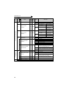
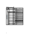
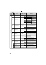
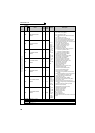
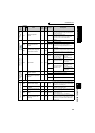
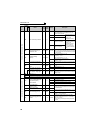
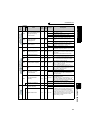
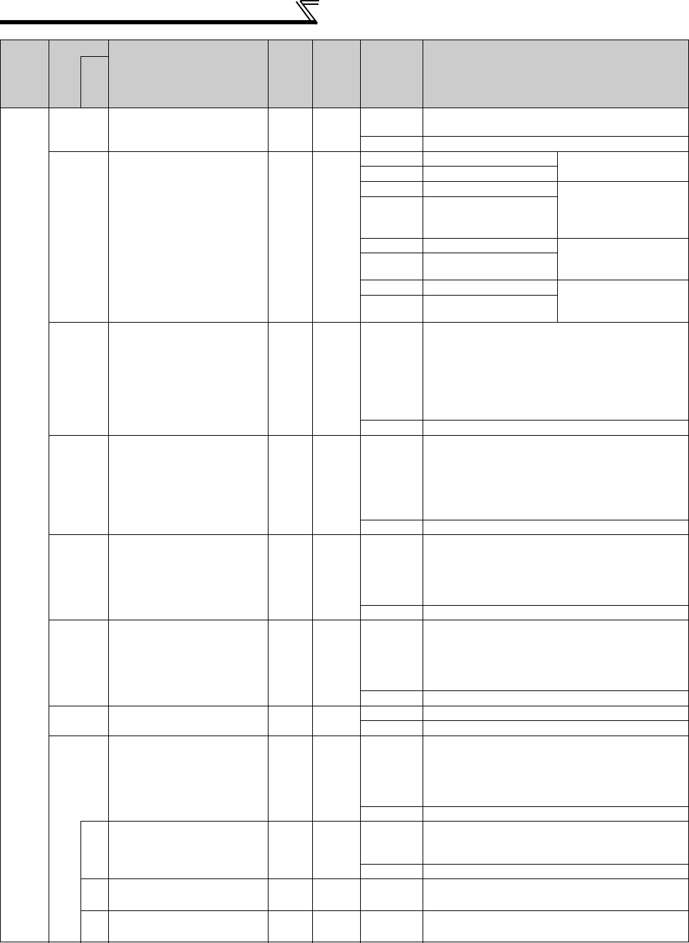
Parameter List
PID control
127
PID control automatic
switchover frequency
0.01Hz 9999
0 to 400Hz
Set the frequency at which the control is
automatically changed to PID control.
9999 Without PID automatic switchover function
128
PID action selection
110
10 PID reverse action
Deviation value signal
(terminal 1)
11 PID forward action
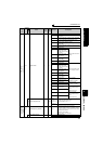
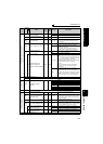
20 PID reverse action Measured value input
(terminal 4)
Set value (terminal 2 or
Pr. 133)
21 PID forward action
50 PID reverse action Deviation value signal
input
(L
ON
W
ORKS
, CC-Link
communication)
51 PID forward action
60 PID reverse action Measured value, set
value input
(L
ON
W
ORKS
,
CC-Link communication)
61 PID forward action
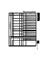
129
PID proportional band
0.1% 100%
0.1 to 1000%
If the proportional band is narrow (parameter setting
is small), the manipulated variable varies greatly with
a slight change of the measured value. Hence, as the
proportional band narrows, the response sensitivity
(gain) improves but the stability deteriorates, e.g.
hunting occurs.
Gain K = 1/proportional band
9999 No proportional control
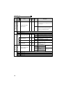
130
PID integral time
0.1s 1s
0.1 to 3600s
When deviation step is input, time (Ti) is the time
required for only the integral (I) action to provide the
same manipulated variable as that for the
proportional (P) action. As the integral time
decreases, the set point is reached earlier but
hunting occurs more easily.
9999 No integral control.
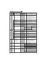
131
PID upper limit
0.1% 9999
0 to 100%
Set the upper limit value.
If the feedback value exceeds the setting, the FUP
signal is output. The maximum input (20mA/5V/10V)
of the measured value (terminal 4) is equivalent to
100%.
9999 No function
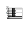
132
PID lower limit
0.1% 9999
0 to 100%
Set the lower limit value.
If the measured value falls below the setting range,
the FDN signal is output.
The maximum input (20mA/5V/10V) of the measured
value (terminal 4) is equivalent to 100%.
9999 No function
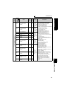
133
PID action set point
0.01% 9999
0 to 100% Used to set the set point for PID control.
9999 Terminal 2 input voltage is the set point.
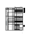
134
PID differential time
0.01s 9999
0.01 to
10.00s
For deviation lamp input, time (Td) required for
providing only the manipulated variable for the
proportional (P) action. As the differential time
increases, greater response is made to a deviation
change.
9999 No differential control.
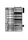
575
Output interruption
detection time
0.1s 1s
0 to 3600s
If the output frequency after PID operation remains
lower than the Pr. 576 setting for longer than the time
set in Pr. 575, the inverter stops operation.
9999 Without output interruption function
576
Output interruption detection
level
0.01Hz 0Hz 0 to 400Hz
Set the frequency at which the output interruption
processing is performed.
577
Output interruption cancel
level
0.1% 1000%
900 to 1100%
Set the level (
Pr. 577
-1000%) to release the PID
output interruption function.
Func
t
ion
Parameter
Name
Incre
ments
Initial
Value
Range Description
Related
parameters