


147
Causes and corrective actions
5
TROUBLESHOOTING
(3) Alarm
When an alarm occurs, the output is not shut off. You can also output an alarm signal by making parameter
setting. (Set "98" in any of Pr. 190 to Pr. 196 (output terminal function selection). (Refer to Chapter 4 of the
Instruction Manual (Applied).))
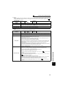
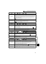
(4) Fault
When a fault occurs, the inverter trips and a fault signal is output.
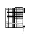
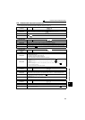
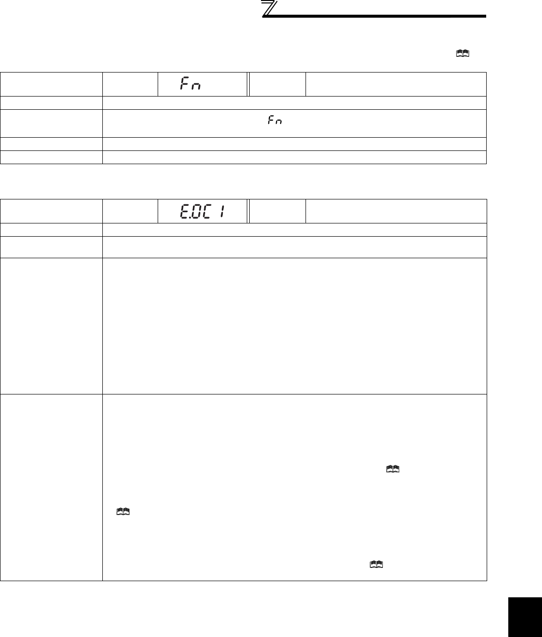
Operation Panel
Indication
FN
FR-PU04
FR-PU07
FN
Name
Fan alarm
Description
For the inverter that contains a cooling fan, appears on the operation panel when the cooling fan
stops due to a fault or different operation from the setting of Pr. 244 Cooling fan operation selection.
Check point
Check the cooling fan for a fault.
Corrective action Check for fan fault. Please contact your sales representative.
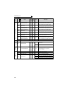
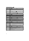
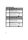
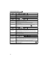
Operation Panel
Indication
E.OC1
FR-PU04
FR-PU07
OC During Acc
Name
Overcurrent trip during acceleration
Description
When the inverter output current reaches or exceeds approximately 220% of the rated current during
acceleration, the protective circuit is activated to stop the inverter output.
Check point
y Check for sudden acceleration.
y Check that the downward acceleration time is not long for lift.
y Check for output short circuit.
y Check that the Pr. 3 Base frequency setting is not 60Hz when the motor rated frequency is 50Hz.
y Check if the stall prevention operation level is set too high.
y Check if the fast-response current limit operation is disabled.
y Check that the regeneration is not performed frequently. (Check that the output voltage becomes
larger than the V/F reference voltage at regeneration and overcurrent due to increase in motor
current occurs.)
y Check that the power supply for RS-485 terminal is not shorted. (under vector control)
y Check that the rotation direction is not switched from forward to reverse rotation (or from reverse to
forward) during torque control under Real sensorless vector control.
y Check if a start command is given to the inverter while the motor is coasting.
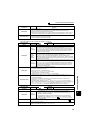
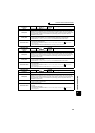
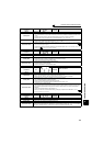
Corrective action
y Increase the acceleration time.
(Shorten the downward acceleration time for lift.)
y When "E.OC1" is always lit at starting, disconnect the motor once and start the inverter.
If "E.OC1" is still lit, contact your sales representative.
y Check the wiring to make sure that output short circuit does not occur.
y Set the Pr. 3 Base frequency to 50Hz. (Refer to page 58.)
y Lower the setting of stall prevention operation level. (Refer to Chapter 4 of the Instruction Manual
(Applied).)
y Activate the fast-response current limit operation.
y Set base voltage (rated voltage of the motor, etc.) in Pr. 19 Base frequency voltage. (Refer to Chapter 4 of
the Instruction Manual (Applied).)
y Check RS-485 terminal connection. (under vector control)
y Prevent the motor from switching the rotation direction from forward to reverse (or from reverse to
forward) during torque control under Real sensorless vector control.
y Input a start command after the motor stops. Alternatively, set the automatic restart after
instantaneous power failure/flying start function. (Refer to Chapter 4 of the Instruction Manual
(Applied).)