


126
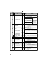
Parameter List
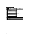
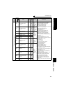
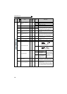
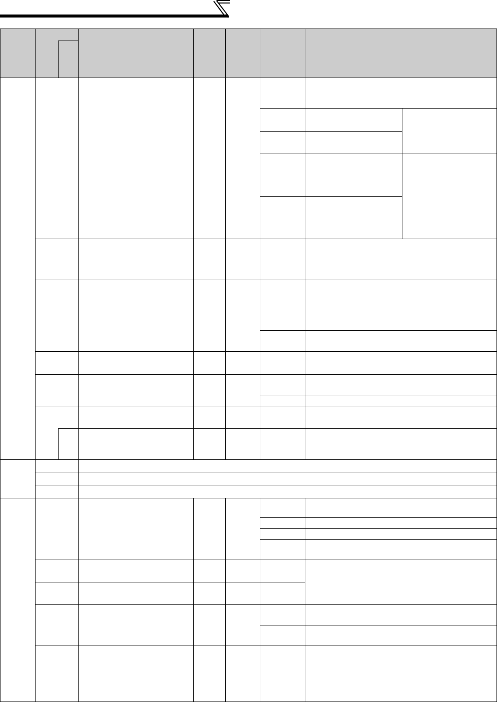
Operation at instantaneous power failure
261
Power failure stop selection
10
0
Coasting to stop
When undervoltage or power failure occurs, the
inverter output is shut off.
1 Without UV avoidance
When undervoltage or a
power failure occurs, the
inverter can be
decelerated to a stop.
11 With UV avoidance
2 Without UV avoidance
When undervoltage or a
power failure occurs, the
inverter can be
decelerated to a stop.
If power is restored
during a power failure,
the inverter accelerates
again.
12 With UV avoidance
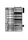
262
Subtracted frequency at
deceleration start
0.01Hz 3Hz 0 to 20Hz
Normally operation can be performed with the initial
value unchanged. But adjust the frequency according
to the magnitude of the load specifications (moment
of inertia, torque).
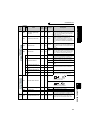
263
Subtraction starting
frequency
0.01Hz 60Hz
0 to 120Hz
When output frequency ≥ Pr. 263
Decelerate from the speed obtained from output
frequency - Pr. 262.
When output frequency < Pr. 263
Decelerate from output frequency
9999
Decelerate from the speed obtained from output
frequency - Pr. 262.
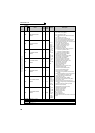
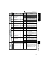
264
Power-failure deceleration
time 1
0.1/
0.01s
5s
0 to 3600/
360s
Set a deceleration slope down to the frequency set in
Pr. 266.
265
Power-failure deceleration
time 2
0.1/
0.01s
9999
0 to 3600/
360s
Set a deceleration slope below the frequency set in
Pr. 266.
9999 Same slope as in Pr. 264
266
Power failure deceleration
time switchover frequency
0.01Hz 60Hz 0 to 400Hz
Set the frequency at which the deceleration slope is
switched from the Pr. 264 setting to the Pr. 265 setting.
294
UV avoidance voltage gain
0.1% 100% 0 to 200%
Adjust response level at UV avoidance operation. A
larger setting will improve responsiveness to the bus
voltage change.
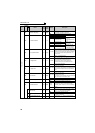
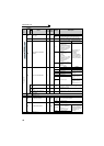
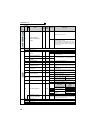
—
267
Refer to Pr. 73.
268
Refer to Pr. 52.
269
Parameter for manufacturer setting. Do not set.
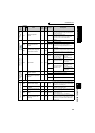
Load torque high speed frequency control
270
Stop-on contact/load torque
high-speed frequency
control selection
10
0
Without stop-on contact control and load torque high-
speed frequency control
1 Stop-on contact control
2 Load torque high speed frequency control
3
Stop-on contact + load torque high speed frequency
control
271
High-speed setting
maximum current
0.1% 50% 0 to 220%
Set the upper and lower limits of the current at high
and middle speeds.
272
Middle-speed setting
minimum current
0.1% 100% 0 to 220%
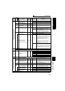
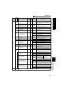
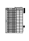
273
Current averaging range
0.01Hz 9999
0 to 400Hz
Average current during acceleration from (Pr. 273
× 1/
2)Hz to (Pr. 273 )Hz can be achieved.
9999
Average current during acceleration from (Pr. 5
× 1/
2)Hz to (Pr. 5 )Hz is achieved.
274
Current averaging filter time
constant
1 16 1 to 4000
Set the time constant of the primary delay filter
relative to the output current.
(The time constant [ms] is 0.75
× Pr. 274 and the
initial value is 12ms.)
A larger setting provides higher stability but poorer
response.
Func
t
ion
Parameter
Name
Incre
ments
Initial
Value
Range Description
Related
parameters