


19
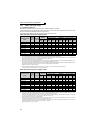
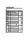
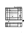
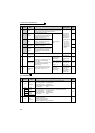
Main circuit terminal specifications
2
WIRING
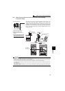
2.2.4 When connecting the control circuit and the main circuit separately
to the power supply
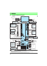
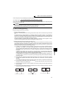
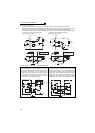
<Connection diagram> When fault occurs, opening of the electromagnetic contactor (MC) on the
inverter power supply side results in power loss in the control circuit,
disabling the fault output signal retention. Terminals R1/L11 and S1/L21 are
provided to hold a fault signal. In this case, connect the power supply
terminals R1/L11 and S1/L21 of the control circuit to the input side of the MC.
Do not connect the power cable to incorrect terminals. Doing so may
damage the inverter.
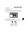
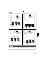
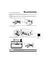
1)Remove the upper screws.
2)Remove the lower screws.
3)Pull the jumper toward you to
remove.
4)
Connect the separate power supply
cable for the control circuit to the
upper terminals (R1/L11, S1/L21).
CAUTION
· Do not turn off the control power (terminals R1/L11 and S1/L21) with the main circuit power (R/L1, S/L2, T/L3) on. Doing so may
damage the inverter. Make up a circuit which will switch off the main circuit power supply terminals R/L1, S/L2, T/L3 when the
control circuit power supply terminals R1/L11, S1/L21 are switched off.
· Be sure to use the inverter with the jumpers across terminals R/L1 and R1/L11 and across terminals S/L2 and S1/L21 removed
when supplying power from other sources. The inverter may be damaged if you do not remove the jumper.
· The voltage should be the same as that of the main control circuit when the control circuit power is supplied from other than the
input side of the MC.
· When separate power is supplied from R1/L11 and S1/L21, the power capacity necessary for the 15K or lower is 90VA, for the
18.5K or higher is 100VA.
· If the main circuit power is switched OFF (for 0.1s or more) then ON again, the inverter resets and a fault output will not be held.
Inverter
MC
R/L1
S/L2
T/L3
R1/L11
S1/L21
Remove the jumper
S1/L21
R1/L11
3)
4)
1)
2)
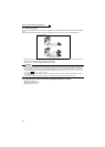
Power supply
terminal block for
the control circuit
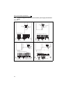
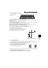
Power supply terminal block
for the control circuit
R/L1
S/L2
T/L3
R1/
L11
S1/
L21
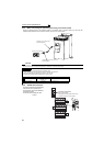
Power supply
terminal block
for the control circuit
Main power supply
MC
FR-A721-5.5K to 15K
FR-A741-5.5K to 15K
FR-A721-18.5K to 55K
FR-A741-18.5K to 55K