


164
Check first when you have a trouble
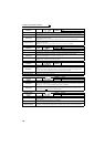
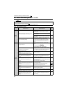
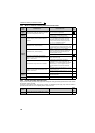
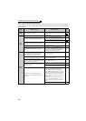
5.6.2 Motor or machine is making abnormal acoustic noise
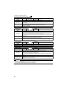
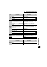
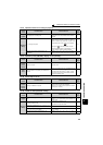
5.6.3 Inverter generates abnormal noise
Larger acoustic noise is generated during regenerative driving than during power driving because the inverter contains
an AC reactor. This is not a fault.
Connecting a single-phase power supply device or having an unbalanced power supply may cause the reactor to
generate acoustic noise even in non-operating status. This is not a fault.
Check
points
Possible Cause Countermeasures
Refer
to
page
Input
signal
Disturbance due to EMI when frequency command
is given from analog input (terminal 1, 2, 4).
Take countermeasures against EMI.
Parameter
Setting
Increase the Pr. 74 Input filter time constant if steady
operation cannot be performed due to EMI.
114
Parameter
Setting
No carrier frequency noises (metallic noises) are
generated.
In the initial setting, Pr. 240 Soft-PWM operation
selection is enabled to change motor noise to an
unoffending complex tone. Therefore, no carrier
frequency noises (metallic noises) are generated.
Set Pr. 240 = "0" to disable this function.
113
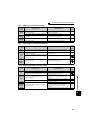
Resonance occurs. (output frequency)
Set Pr. 31 to Pr. 36 (Frequency jump).
When it is desired to avoid resonance attributable to
the natural frequency of a mechanical system, these
parameters allow resonant frequencies to be jumped.
108
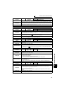
Resonance occurs. (carrier frequency)
Change Pr. 72 PWM frequency selection setting.
Changing the PWM carrier frequency produces an
effect on avoiding the resonance frequency of a
mechanical system or a motor.
113
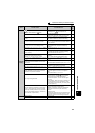
Set a notch filter.
Auto tuning is not performed under Advanced
magnetic flux vector control, Real sensorless vector
control, or vector control.
Perform offline auto tuning. 71
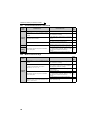
Gain adjustment during PID control is insufficient.
To stabilize the measured value, change the
proportional band (Pr. 129) to a larger value, the
integral time (Pr. 130) to a slightly longer time, and the
differential time (Pr. 134) to a slightly shorter time.
Check the calibration of set point and measured
value.
120
The gain is too high under Real sensorless vector
control or vector control.
During speed control, check the setting of Pr. 820 (Pr.
830) speed control P gain.
135
During torque control, check the setting of Pr. 824 (Pr.
834) torque control P gain.
136
Others
Mechanical looseness
Adjust machine/equipment so that there is no
mechanical looseness.
—
Contact the motor manufacturer.
Motor
Operating with output phase loss Check the motor wiring. —
Check
points
Possible Cause Countermeasures
Refer
to
page
Fan
Fan cover was not correctly installed when a cooling
fan was replaced.
Install a fan cover correctly. 175