132
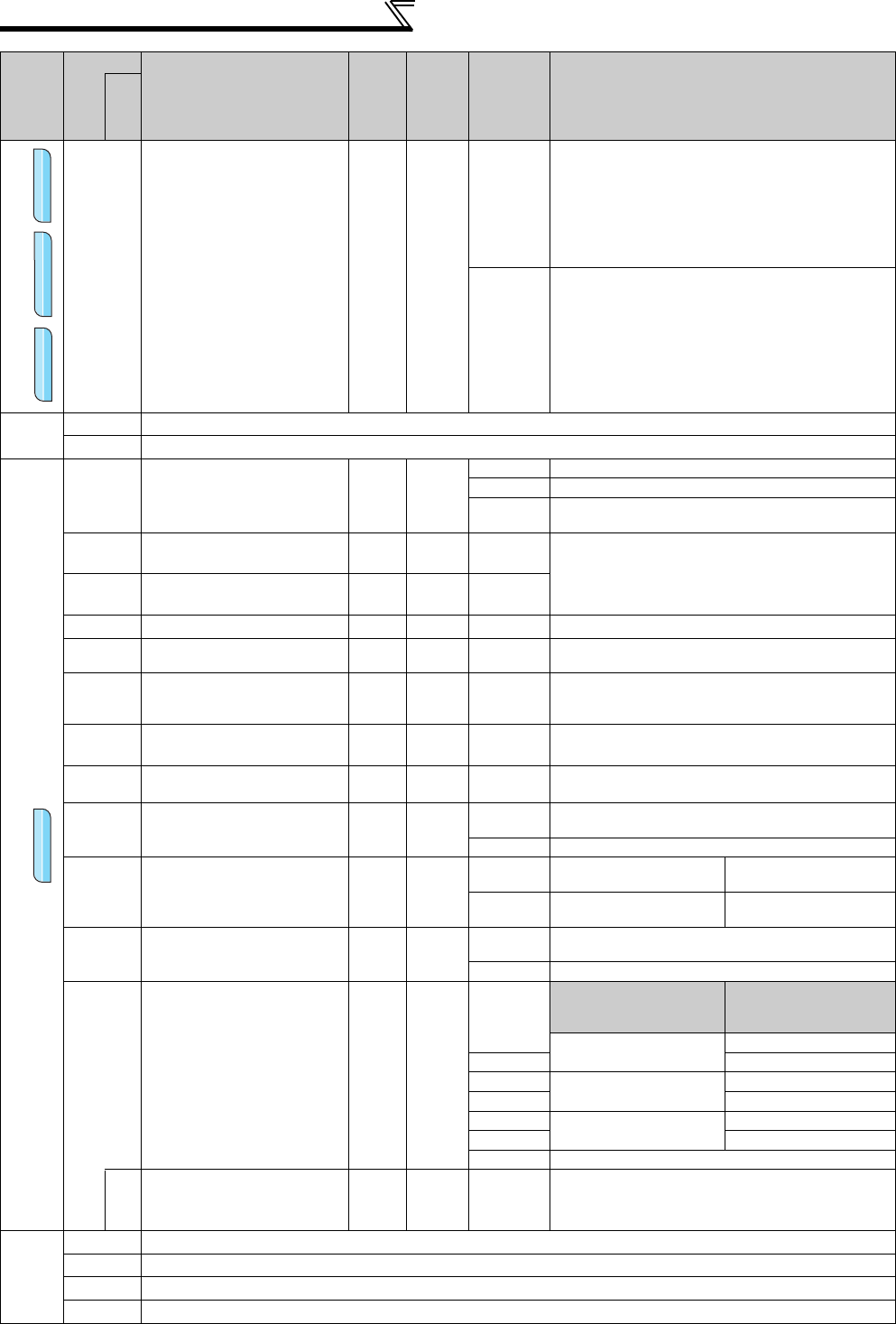
Parameter List
Encoder signal loss detection
376
Encoder signal loss
detection enable/disable
selection
10
0
Signal loss detection is invalid
1
Signal loss detection is valid
When the cable of the encoder signal is broken during
encoder feedback control, orientation control, or vector
control, signal loss detection (E.ECT) is activated to stop
the inverter output.
—
380 to 383
Refer to Pr. 29.
384 to 386
Refer to Pr. 291.
Position control
419
Position command source
selection
10
0
Simple position control function by contact input
1 Position command using pulse train input (FR-A7AL)
2
Simple position pulse train command by pulse train input
from the JOG terminal
420
Command pulse scaling factor
numerator
1 1 0 to 32767
Set the electronic gear.
Pr. 420 is a numerator and Pr. 421 is a denominator.
421
Command pulse scaling factor
denominator
1 1 0 to 32767
422
Position loop gain
1s
-1
25s
-1
0 to 150s
-1
Set the gain of the position loop.
423
Position feed forward gain
1% 0% 0 to 100%
Function to cancel a delay caused by the droop pulses of
the deviation counter.
424
Position command acceleration/
deceleration time constant
0.001s 0s 0 to 50s
Used when rotation has become unsmooth at a large
electronic gear ratio (about 10 times or more) and low
speed.
425
Position feed forward
command filter
0.001s 0s 0 to 5s
Enters the primary delay filter in response to the feed
forward command.
426
In-position width
1 pulse
100
pulse
0 to 32767
pulse
The in-position signal (Y36) turns on when the droop
pulses become less than the setting.
427
Excessive level error
1 40K
0 to 400K
A position error excessive (E.OD) occurs when the droop
pulses exceed the setting.
9999
Function invalid
428
Command pulse selection
10
0 to 2
Pulse train + rotation signal
sign
Negative logic
3 to 5
Pulse train + rotation signal
sign
Positive logic
429
Clear signal selection
11
0
Deviation counter is cleared at trailing edge (at the
moment when H level is changed to L level)
1 eviation counter is cleared at L level
430
Pulse monitor selection
1 9999
Description
FR-DU07(FR-PU04/FR-
PU07)
display
0
The cumulative command
pulse value is displayed.
Lower 4(5) digits
1 Upper 4(5) digits
2
The cumulative feedback
pulse value is displayed.
Lower 4(5) digits
3 Upper 4(5) digits
4
The droop pulses are
monitored.
Lower 4(5) digits
5 Upper 4(5) digits
9999
Frequency monitor is displayed.
464
Digital position control
sudden stop deceleration
time
0.1s 0 0 to 360.0s
Set the time until the inverter stops when the forward
rotation (reverse rotation) command is turned OFF with
the position feed forward function.
—
450
Refer to Pr. 71.
451
Refer to Pr. 80.
453, 454
Refer to Pr. 80.
455 to 463
Refer to Pr. 82.
Func
t
ion
Parameter
Name
Incre
ments
Initial
Value
Range Description
Related
parameters
V/F
V/F
Magnetic flux
Magnetic flux
Vector
VectorVector
Vector


