


152
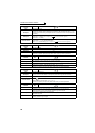
Causes and corrective actions
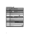
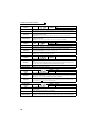
Operation Panel
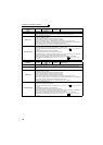
Indication
E.GF
FR-PU04
FR-PU07
Ground Fault
Name
Output side earth (ground) fault overcurrent
Description
This function stops the inverter output if an earth (ground) fault overcurrent flows due to an earth
(ground) fault that occurred on the inverter's output (load) side.
Check point Check for an earth (ground) fault in the motor and connection cable.
Corrective action
Remedy the earth (ground) fault portion.
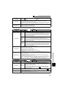
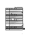
Operation Panel
Indication
E.LF
FR-PU04
FR-PU07
E. LF
Name
Output phase loss
Description
This function stops the inverter output if one of the three phases (U, V, W) on the inverter's output side
(load side) is lost.
Check point
y Check the wiring (Check that the motor is normal.)
y Check that the capacity of the motor used is not smaller than that of the inverter.
y Check if a start command is given to the inverter while the motor is coasting.
Corrective action
y Wire the cables properly.
y Check the Pr. 251 Output phase loss protection selection setting.
y Input a start command after the motor stops. Alternatively, set the automatic restart after
instantaneous power failure/flying start function. (Refer to Chapter 4 of the Instruction Manual
(Applied).)
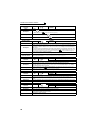
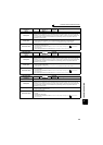
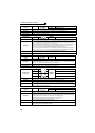
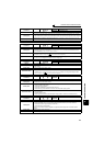
Operation Panel
Indication
E.OHT
FR-PU04
FR-PU07
OH Fault
Name
External thermal relay operation
Description
If the external thermal relay provided for motor overheat protection, or the internally mounted
temperature relay in the motor, etc. switches on (contacts open), the inverter output is stopped.
This function is available when "7" (OH signal) is set in any of Pr. 178 to Pr. 189 (input terminal function
selection).
When the initial value (without OH signal assigned) is set, this protective function is not available.
Check point
y Check for motor overheating.
y
Check that the value of 7 (OH signal) is set correctly in any of
Pr. 178 to Pr. 189 (input terminal function selection)
.
Corrective action
y Reduce the load and operating duty.
y Even if the relay contacts are reset automatically, the inverter will not restart unless it is reset.
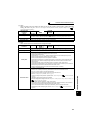
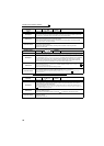
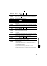
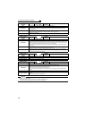
Operation Panel
Indication
E.PTC
FR-PU04 Fault 14
FR-PU07 PTC activated
Name
PTC thermistor operation
Description
Stops the inverter output when the motor overheat status is detected for 10s or more by the external
PTC thermistor input connected to the terminal AU.
This fault is available when "63" is set in Pr. 184 AU terminal function selection and AU/PTC switchover
switch is set in PTC side. When the initial value (Pr. 184 = "4") is set, this protective function is not
available.
Check point
y Check the connection between the PTC thermistor switch and thermal protector.
y Check the motor for operation under overload.
y Is valid setting ( = 63) selected in Pr. 184 AU terminal function selection ? (Refer to Chapter 4 of the
Instruction Manual (Applied).)
Corrective action
Reduce the load weight.