


2
Inverter and peripheral devices
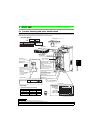
1.2 Inverter and peripheral devices
CAUTION
·
Do not install a power factor correction capacitor, surge suppressor or radio noise filter on the inverter output side. This will cause the
inverter to trip or the capacitor, and surge suppressor to be damaged. If any of the above devices are connected, immediately remove them.
· This inverter has a built-in AC reactor (FR-HAL) and a circuit type specified in Harmonic suppression guideline in Japan is three-
phase bridge (capacitor smoothed) and with reactor (AC side). (Refer to page 39) Do not use an AC reactor (FR-HAL) of a stand-
alone option except following purpose. (Note that overload protection of the converter may operate when a thyristor load is
connected in the power supply system. To prevent this, always install an optional stand-alone AC reactor (FR-HAL).) A DC
reactor (FR-HEL) can not be connected to the inverter.
· Electromagnetic wave interference
The input/output (main circuit) of the inverter includes high frequency components, which may interfere with the communication
devices (such as AM radios) used near the inverter. In this case, connecting a capacitor type filter will reduce electromagnetic
wave interference.
· Refer to the instruction manual of each option and peripheral devices for details of peripheral devices.
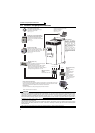
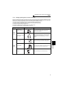
Motor
Devices connected to the output
EMC filter (ferrite core)
(FR-BLF)
Install a noise filter to
reduce the
electromagnetic noise
generated from the
inverter.
Effective in the range
from about 1MHz to
10MHz. A wire should be
wound four turns at a
maximum.
Three-phase AC power supply
Use within the permissible power supply
specifications of the inverter.
Moulded case circuit breaker (MCCB) or
earth leakage circuit breaker (ELB), fuse
The breaker must be selected carefully
since an in-rush current flows in the inverter
at power on.
Magnetic contactor (MC)
Install the magnetic contactor to ensure
safety. Do not use this magnetic contactor
to start and stop the inverter. Doing so will
cause the inverter life to be shorten.
Do not install a power factor correction capacitor, surge suppressor or radio noise filter on the output
side of the inverter. When installing a moulded case circuit breaker on the output side of the inverter,
contact each manufacturer for selection of the moulded case circuit breaker.
UWV
EMC filter (ferrite core)
(FR-BLF)
Install a noise filter to reduce the electromagnetic
noise generated from the inverter.
Effective in the range from about 1MHz to 10MHz.
When more wires are passed through, a more
effective result can be obtained. The total number of
wires passed through should be 4T or more.
Earth (Ground)
Earth (Ground)
To prevent an electric shock, always earth (ground) the motor and inverter.
Earth
(Ground)
EMC filter (capacitor)
(FR-BIF)
Reduces the radio noise.
: Install these options as required.
R/L1 S/L2 T/L3
USB connector
A personal computer and an inverter
can be connected with a
USB (Ver1. 1) cable.
(Refer to page 182)
(Refer to page 3)
(Refer to page 3)
Inverter (FR-A701)
The life of the inverter is
influenced by surrounding air
temperature. The surrounding
air temperature should be as low
as possible within the
permissible range. This must be
noted especially when the
inverter is installed in an
enclosure. (Refer to page 6)
Wrong wiring might lead to
damage of the inverter. The
control signal lines must be kept
fully away from the main circuit
to protect them from noise.(Refer
to page 12)
(Refer to page 27)