27/28 BCN-C22005-675
(4) FR-A7NF
The communication option FR-A7NF is supported. When the FR-A7NF is used for the FR-A701 series, the inverter is oper-
ated in the PU operation interlock (X12 signal) specification. For the details of FR-A7NF, refer to the Instruction Manual of
FR-A7NF.
(5) FR-A701 dedicated monitor code / fault code for communication options
The FR-A701 dedicated monitor codes and the fault codes when the communication options are used are as shown below.
• Monitor code
• Fault code (fault data)
11 Regenerative operation stop signal (X75 signal)
• The converter operation stops when the X75 signal is turned ON during an inverter stop.
• When the regenerative status is entered during a converter stop, the protective function (E.OV) is activated due to
overvoltage, and the inverter trips.
• To apply the X75 signal status to the converter operation, it is necessary to stop the inverter.
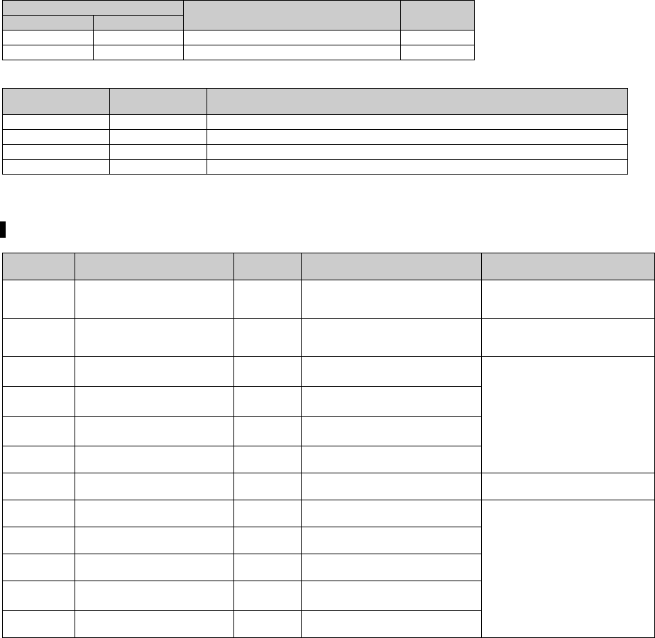
Code Number
Monitor Description Increments
FR-A7NCE FR-A7NF
H41 H10000210 Output power (with regenerative display) 0.1kW
H42 H10000212 Cumulative regenerative power 1kWh
Fault code (data)
Fault indication
(description)
Fault name
HF4 E.4 Fault 4 (Converter overcurrent)
HF8 E.8 Fault 8 (Power supply fault)
HFA E.10 Fault 10 (Converter transistor protection thermal operation (electronic thermal))
HFF E.15 Fault 15 (Convertor circuit fault)
The converter operation can be stopped by turning ON the X75 signal.
Parameter
Number
Name
Initial
Value
Initial signal Setting Range
178
STF terminal function
selection
60 STF (Forward rotation command)
0 to 9, 12 to 20, 22 to 28, 42 to
44, 60, 62, 64 to 69, 74, 75,
9999
179
STR terminal function
selection
61
STR (Reverse rotation
command)
0 to 9, 12 to 20, 23 to 28, 42 to
44, 61, 62, 64 to 69, 74, 75,
9999
180
RL terminal function
selection
0
RL (Low-speed operation
command)
0 to 9, 12 to 20, 22 to 28, 42 to
44, 62, 64 to 69, 74, 75, 9999
181
RM terminal function
selection
1
RM (Middle-speed operation
command)
182
RH terminal function
selection
2
RH (High-speed operation
command)
183
RT terminal function
selection
3 RT (Second function selection)
184
AU terminal function
selection
4 AU (Terminal 4 input selection)
0 to 9, 12 to 20, 22 to 28, 42 to
44, 62 to 69, 74, 75, 9999
185
JOG terminal function
selection
5 JOG (Jog operation selection)
0 to 9, 12 to 20, 22 to 28, 42 to
44, 62, 64 to 69, 74, 75, 9999
186
CS terminal function
selection
6 CS (Electronic bypass function)
187
MRS terminal function
selection
24 MRS (Output stop)
188
STOP terminal function
selection
25
STOP (Start self-holding
selection)
189
RES terminal function
selection
62 RES (Inverter reset)
bcnc22005635.fm 27 ページ 2014年12月11日 木曜日 午後5時59分


