


200
(5) Motor overload protection
This inverter is certified as a motor overload protection device by UL.
When using the electronic thermal relay function as motor overload protection, set the rated motor current to Pr. 9
Electronic thermal O/L relay.
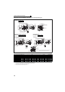
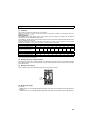
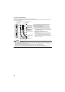
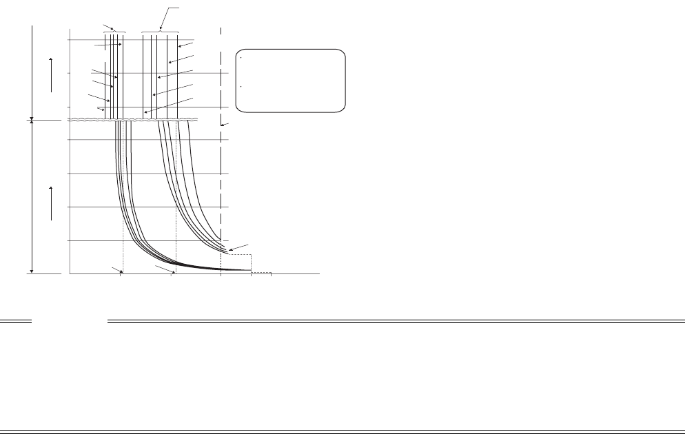
Electronic thermal relay function operation characteristic
This function detects the overload (overheat) of the
motor, stops the operation of the inverter's output
transistor, and stops the output.
(The operation characteristic is shown on the left)
When using the Mitsubishi constant-torque motor
1) Set "1" or any of "13" to "18", "50", "53", "54" in
Pr. 71
.
(This provides a 100% continuous torque characteristic
in the low-speed range.)
2) Set the rated current of the motor in Pr. 9.
*1 When a value 50% of the inverter rated output current (current
value) is set in Pr. 9
*2 The % value denotes the percentage to the inverter rated output
current. It is not the percentage to the motor rated current.
*3 When you set the electronic thermal relay function dedicated to the
Mitsubishi constant-torque motor, this characteristic curve applies
to operation at 6Hz or higher.
CAUTION
⋅ Protective function by electronic thermal relay function is reset by inverter power reset and reset signal input. Avoid
unnecessary reset and power-off.
⋅ When multiple motors are operated by a single inverter, protection cannot be provided by the electronic thermal relay function.
Install an external thermal relay to each motor.
⋅ When the difference between the inverter and motor capacities is large and the setting is small, the protective characteristics of
the electronic thermal relay function will be deteriorated. In this case, use an external thermal relay.
⋅ A special motor cannot be protected by the electronic thermal relay function. Use the external thermal relay.
⋅ Electronic thermal relay does not function when 5% or less of inverter rated current is set to electronic thermal relay setting.
For transistor protection
Electronic thermal relay
function
52.5%
105%
50
100
150
60
120
180
240
50
60
70
6Hz
20Hz
10Hz
6Hz
0.5Hz
30Hz or more*
3
20Hz
10Hz
0.5Hz
Pr. 9 = 50% setting of
inverter rating*
1.2
Pr. 9 = 100% setting
of inverter rating*
1.2
(s) unit display in this range
(min) unit display in
this range
Operation time (min)Operation time (s)
Characteristic when
electronic thermal relay
function for motor
protection is turned OFF
(When Pr. 9 setting is 0(A))
30Hz
or more*
3
Inverter output power (%)
(% to the rated input current)
Operation range
Range on the right of
characteristic curve
Non-operation range
Range on the left of
characteristic curve