


25
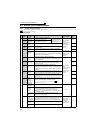
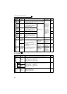
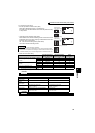
Control circuit specifications
2
WIRING
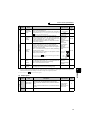
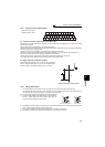
2.3.3 Control circuit terminal layout
(1) Common terminals of the control circuit (SD, 5, SE)
Terminals SD, 5, and SE are all common terminals (0V) for I/O signals and are isolated from each other. Do not earth
(ground) these terminals.
Avoid connecting the terminal SD and 5 and the terminal SE and 5.
Terminal SD is a common terminal for the contact input terminals (STF, STR, STOP, RH, RM, RL, JOG, RT, MRS, RES,
AU, CS) and frequency output signal (FM).
The open collector circuit is isolated from the internal control circuit by photocoupler.
Terminal 5 is a common terminal for frequency setting signal (terminal 2, 1 or 4) and analog output terminal AM.
It should be protected from external noise using a shielded or twisted cable.
Terminal SE is a common terminal for the open collector output terminal (RUN, SU, OL, IPF, FU).
The contact input circuit is isolated from the internal control circuit by photocoupler.
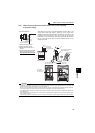
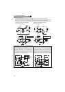
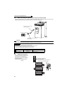
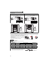
(2) Signal inputs by contactless switches
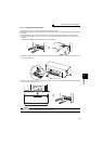
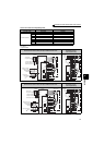
2.3.4 Wiring instructions
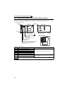
1) It is recommended to use the cables of 0.75mm
2
gauge for connection to the control circuit terminals.
If the cable gauge used is 1.25mm
2
or more, the front cover may be lifted when there are many cables running or
the cables are run improperly, resulting in an operation panel contact fault.
2) The wiring length should be 30m(200m for terminal FM) maximum.
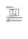
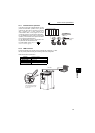
3) Use two or more parallel micro-signal contacts or twin contacts to
prevent a contact faults when using contact inputs since the
control circuit input signals are micro-currents.
4) Use shielded or twisted cables for connection to the control circuit terminals and run them away from the main and
power circuits (including the 200V relay sequence circuit).
5) Do not apply a voltage to the contact input terminals (e.g. STF) of the control circuit.
6) Always apply a voltage to the fault output terminals (A, B, C) via a relay coil, lamp, etc.
Terminal screw size: M3.5
Tightening torque: 1.2N·m
The contacted input terminals of the inverter (STF, STR, STOP, RH,
RM, RL, JOG, RT, MRS, RES, AU, CS) can be controlled using a
transistor instead of a contacted switch as shown on the right.
External signal input using transistor
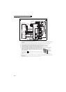
A1 B1 C1 A2 B2 C2 10E 10 2 5 4
1AMSDRES
MRS
STOP
AURTRHRMRL
PCCSJOGSTRSTFSDSDFUOLIPFSURUNSE
FM
+24V
STF, etc
Inverter
SD
Micro signal contacts Twin contacts