


21
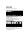
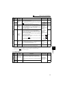
Control circuit specifications
2
WIRING
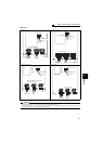
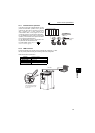
*1 Set Pr. 73, Pr. 267, and a voltage/current input switch correctly, then input an analog signal in accordance with the setting.
Applying a voltage signal with voltage/current input switch ON (current input is selected) or a current signal with switch OFF (voltage input is
selected) could cause component damage of the inverter or analog circuit of signal output devices.
*2 Refer to Chapter 4 of
the Instruction Manual (Applied).
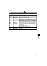
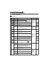
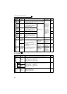
(2) Output signals
Frequency setting
10E
Frequency
setting power
supply
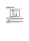
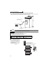
When connecting the frequency setting potentiometer at an initial
status, connect it to terminal 10.
Change the input specifications of terminal 2 when connecting it
to terminal 10E. (Refer to Pr. 73 Analog input selection in Chapter 4 of
the Instruction Manual (Applied).)
10VDC
Permissible load
current 10mA
*2
10
5VDC
Permissible load
current 10mA
88, 96
2
Frequency
setting
(voltage)
Inputting 0 to 5VDC (or 0 to 10V, 0 to 20mA) provides the
maximum output frequency at 5V (10V, 20mA) and makes input
and output proportional. Use Pr. 73 to switch from among input 0
to 5VDC (initial setting), 0 to 10VDC, and 0 to 20mA.
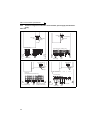
Set the voltage/current input switch in the ON position to select
current input (0 to 20mA).
*1
Voltage input:
Input resistance
10kΩ ± 1kΩ
Maximum
permissible voltage
20VDC
Current input:
Input resistance
245Ω ± 5Ω
Maximum
permissible current
30mA
88, 96
4
Frequency
setting
(current)
Inputting 4 to 20mADC (or 0 to 5V, 0 to 10V) provides the
maximum output frequency at 20mA makes input and output
proportional. This input signal is valid only when the AU signal is
ON (terminal 2 input is invalid).
Use Pr. 267 to switch from among input 4 to 20mA (initial setting),
0 to 5VDC, and 0 to 10VDC.
Set the voltage/current input switch in the OFF position to select
voltage input (0 to 5V/0 to 10V).
*1
(Refer to Chapter 4 of the Instruction Manual (Applied).) Use Pr.
858 to switch terminal functions.
90, 98
1
Frequency
setting
auxiliary
Inputting 0 to ±5 VDC or 0 to ±10VDC adds this signal to terminal
2 or 4 frequency setting signal. Use Pr. 73 to switch between the
input 0 to ±5VDC and 0 to ±10VDC (initial setting).
Use Pr. 868 to switch terminal functions.
Input resistance
10kΩ ± 1kΩ
Maximum
permissible voltage
± 20VDC
*2
5
Frequency
setting
common
Common terminal for frequency setting signal (terminal 2, 1 or 4)
and analog output terminal AM. Do not earth (ground).
-------------------- ------
Type
Terminal
Symbol
Terminal
Name
Description
Rated
Specifications
Refer to
page
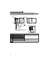
Relay
A1,
B1,
C1
Relay output 1
(alarm output)
1 changeover contact output indicates that the inverter
protective function has activated and the output stopped.
Fault: No conduction between B and C (conduction between A
and C)
Normal: Conduction between B and C (No conduction between
A and C)
Contact capacity:
230VAC 0.3A
(Power factor=0.4)
30VDC 0.3A
*2
A2,
B2,
C2
Relay output 2 1 changeover contact output *2
Type
Terminal
Symbol
Terminal
Name
Description
Rated
Specifications
Refer to
page
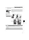
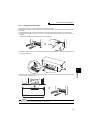
Voltage/current
input switch
2
4
switch1
switch2