


162
Check first when you have a trouble
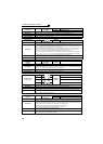
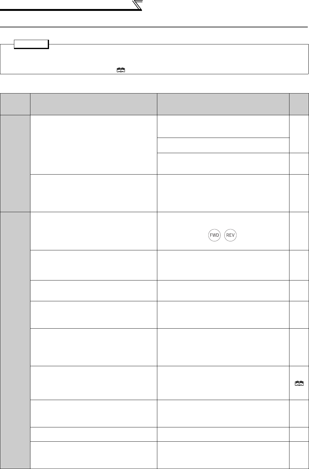
5.6 Check first when you have a trouble
Refer to troubleshooting on page 81 (speed control) in addition to the following check points.
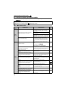
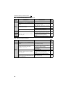
5.6.1 Motor does not start
POINT
· If the cause is still unknown after every check, it is recommended to initialize the parameters (initial value) then reset the
required parameter values and check again.
· Refer to the Instruction Manual (Applied) for in "Refer to page" column.
Check
points
Possible Cause Countermeasures
Refer
to
page
Main
Circuit
Appropriate power supply voltage is not applied.
(Operation panel display is not provided.)
Power ON a moulded case circuit breaker (MCCB), an
earth leakage circuit breaker (ELB), or a magnetic
contactor (MC).
—
Check for the decreased input voltage, input phase
loss, and wiring.
If only the control power is ON when using a separate
power source for the control circuit, turn ON the main
circuit power.
19
Motor is not connected properly.
Check the wiring between the inverter and the motor.
If commercial power supply-inverter switchover
function is active, check the wiring of the magnetic
contactor connected between the inverter and the
motor.
14
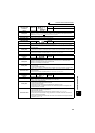
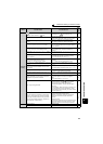
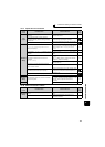
Input
signal
Start signal is not input.
Check the start command source, and input a start
signal.
PU operation mode: /
External operation mode : STF/STR signal
47
Both the forward and reverse rotation start signals
(STF, STR) are input simultaneously.
Turn ON only one of the forward and reverse rotation
start signals (STF or STR).
If STF and STR signals are turned ON simultaneously
in the initial setting, a stop command is given.
20
Frequency command is zero.
(FWD or REV LED on the operation panel is
flickering.)
Check the frequency command source and enter a
frequency command.
47
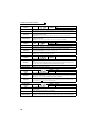
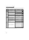
AU signal is not ON when terminal 4 is used for
frequency setting.
(FWD or REV LED on the operation panel is
flickering.)
Turn ON the AU signal.
Turning ON the AU signal activates terminal 4 input.
20
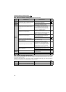
Output stop signal (MRS) or reset signal (RES) is
ON.
(FWD or REV LED on the operation panel is
flickering.)
Turn MRS or RES signal OFF.
Inverter starts the operation with a given start
command and a frequency command after turning OFF
MRS or RES signal.
Before turning OFF, ensure the safety.
20
CS signal is OFF when automatic restart after
instantaneous power failure function is selected (Pr.
57 ≠ "9999").
(FWD or REV LED on the operation panel is
flickering. )
Turn ON the CS signal.
Restart operation is enabled when restart after
instantaneous power signal (CS) is ON.
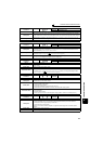
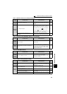
Jumper connector of sink - source is wrongly
selected.
(FWD or REV LED on the operation panel is
flickering.)
Check that the control logic switchover jumper
connector is correctly installed.
If it is not installed correctly, input signal is not recognized.
23
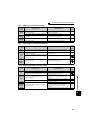
Wiring of encoder is incorrect.
(Under encoder feedback control or vector control)
Check the wiring of encoder. 31
Voltage/current input switch is not correctly set for
analog input signal (0 to 5V/0 to 10V, 4 to 20mA).
(FWD or REV LED on the operation panel is
flickering.)
Set Pr. 73, Pr. 267, and a voltage/current input switch
correctly, then input an analog signal in accordance
with the setting.
20