


158
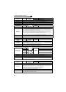
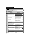
Causes and corrective actions
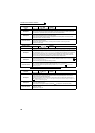
Operation Panel
Indication
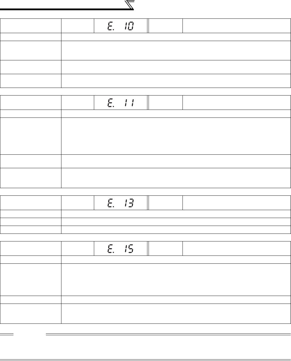
E.10
FR-PU04
FR-PU07
Fault 10
Name
Converter transistor protection thermal operation (electronic thermal)
Description
Current flowing in the module of the regeneration converter is less than the overcurrent shutoff level
and exceeds the specified value, electronic thermal relay activates for protection and the inverter
output is stopped.
Check point
y Check the motor for use under overload. (excess regeneration amount)
y Check that the thyristor load does not exist in the same power supply system.
Corrective action
y Reduce the load weight.
y When a thyristor load exists in the same power supply system, install an AC reactor (FR-HAL).
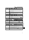
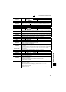
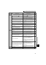
Operation Panel
Indication
E.11
FR-PU04
FR-PU07
Fault 11
Name
Opposite rotation deceleration fault
Description
The speed may not decelerate during low speed operation if the rotation direction of the speed
command and the estimated speed differ when the rotation is changing from forward to reverse or from
reverse to forward during torque control under Real sensorless vector control. At this time, the inverter
output is stopped if the rotation direction will not change, causing overload.
This fault is not available in the initial status (V/F control). (It is available only during Real sensorless
vector control.)
Check point
Check that the rotation direction is not switched from forward to reverse rotation (or from reverse to
forward) during torque control under Real sensorless vector control.
Corrective action
y Prevent the motor from switching the rotation direction from forward to reverse (or from reverse to
forward) during torque control under Real sensorless vector control.
y Please contact your sales representative.
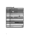
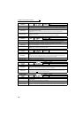
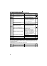
Operation Panel
Indication
E.13
FR-PU04
FR-PU07
Fault 13
Name
Internal circuit fault
Description
Stop the inverter output when an internal circuit fault occurred.
Corrective action
Please contact your sales representative.
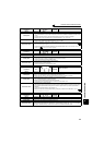
Operation Panel
Indication
E.15
FR-PU04
FR-PU07
Fault 15
Name
Converter circuit fault
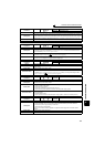
Description
y When a fault occurs in the peripheral circuit of the regeneration converter CPU
y When a fault occurs in the control power supply circuit.
y When a fault occurs in the inrush current limit circuit.
If any of the above conditions applied, it is judged as converter circuit fault and the inverter output is
stopped.
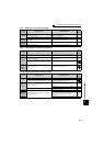
Check point
Check for devices producing excess electrical noises around the inverter.
Corrective action
y Take measures against noises if there are devices producing excess electrical noises around the
inverter.
y Please contact your sales representative.
CAUTION
• If protective functions of E.ILF, E.PTC, E.PE2, E.EP, E.OD, E.CDO, E.IOH, E.SER, E.AIE, E.USB are activated when using the
FR-PU04, "Fault 14" appears.
Also when the faults history is checked on the FR-PU04, the display is "E.14".
• If faults other than the above appear, contact your sales representative.