


2
WIRING
13
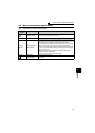
Main circuit terminal specifications
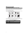
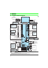
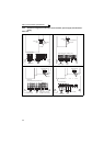
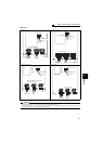
2.2 Main circuit terminal specifications
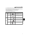
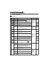
2.2.1 Specification of main circuit terminal
Terminal
Symbol
Terminal Name Description
R/L1,
S/L2,
T/L3
AC power input Connect to the commercial power supply.
U, V, W Inverter output Connect a three-phase squirrel-cage motor.
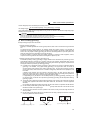
R1/L11,
S1/L21
Power supply for
control circuit
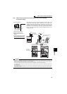
Connected to the AC power supply terminals R/L1 and S/L2. To retain the
fault display and fault output, remove the jumpers from terminals R/L1-R1/
L11 and S/L2-S1/L21 and apply external power to these terminals.
Do not turn off the power supply for control circuit (R1/L11, S1/L21) with the
main circuit power (R/L1, S/L2, T/L3) on. Doing so may damage the
inverter. The circuit should be configured so that the main circuit power (R/
L1, S/L2, T/L3) is also turned off when the power supply for control circuit
(R1/L11, S1/L21) is off.
The following power supply capacities are required to supply power
separately from R1/L11 and S1/L21:
90VA for 15K or lower, 100VA for 18.5K or higher
P/+, N/- DC terminal Do not connect any options.
Earth (Ground)
For earthing (grounding) the inverter chassis. Must be earthed
(grounded).