


17
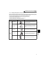
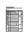
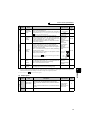
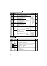
Main circuit terminal specifications
2
WIRING
The line voltage drop can be calculated by the following formula:
Line voltage drop [V]=
Use a larger diameter cable when the wiring distance is long or when it is desired to decrease the voltage drop (torque
reduction) in the low speed range.
CAUTION
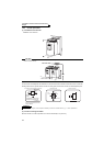
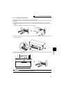
· Tighten the terminal screw to the specified torque.
A screw that has been tighten too loosely can cause a short circuit or malfunction.
A screw that has been tighten too tightly can cause a short circuit or malfunction due to the unit breakage.
· Use crimping terminals with insulation sleeve to wire the power supply and motor.
(2) Notes on earthing (grounding)
z Always earth (ground) the motor and inverter.
1)Purpose of earthing (grounding)
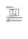
Generally, an electrical apparatus has an earth (ground) terminal, which must be connected to the ground before
use.
An electrical circuit is usually insulated by an insulating material and encased. However, it is impossible to
manufacture an insulating material that can shut off a leakage current completely, and actually, a slight current flow
into the case. The purpose of earthing (grounding) the case of an electrical apparatus is to prevent operator from
getting an electric shock from this leakage current when touching it.
To avoid the influence of external noises, this earthing (grounding) is important to audio equipment, sensors,
computers and other apparatuses that handle low-level signals or operate very fast.
2)Earthing (grounding) methods and earthing (grounding) work
As described previously, earthing (grounding) is roughly classified into an electrical shock prevention type and a
noise-affected malfunction prevention type. Therefore, these two types should be discriminated clearly, and the
following work must be done to prevent the leakage current having the inverter's high frequency components from
entering the malfunction prevention type earthing (grounding):
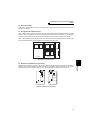
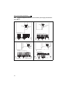
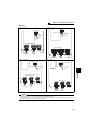
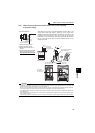
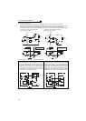
(a) If possible, use (l) independent earthing (grounding) in figure below for the inverter. If independent earthing
(grounding) is not available, use (ll) joint earthing (grounding) in the figure below which the inverter is
connected with the other equipment at an earthing (grounding) point. The (lll) common earthing (grounding)
as in the figure below, which inverter shares a common earth (ground) cable with the other equipment, must
be avoided.
A leakage current including many high frequency components flows in the earth (ground) cables of the
inverter and inverter-driven motor. Therefore, use the independent earthing (grounding) and separated the
earthing (grounding) cable of the inverter from equipments sensitive to EMI.
In a high building, it may be effective to use the EMI prevention type earthing (grounding) connecting to an
iron structure frame, and electric shock prevention type earthing (grounding) with the independent earthing
(grounding) together.
(b) This inverter must be earthed (grounded). Earthing (Grounding) must conform to the requirements of national
and local safety regulations and electrical codes. (NEC section 250, IEC 536 class 1 and other applicable
standards).
Use a neutral-point earthed (grounded) power supply for 400V class inverter in compliance with EN standard.
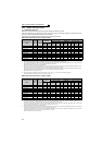
(c) Use the thickest possible earth (ground) cable. The earth
(ground) cable should be of not less than the size
indicated in the table on the previous page.
(d) The grounding point should be as near as possible to the inverter, and the ground wire length should be as
short as possible.
(e) Run the earth (ground) cable as far away as possible from the I/O wiring of equipment sensitive to noises and
run them in parallel in the minimum distance.
3 × wire resistance[mΩ/m] × wiring distance[m] × current[A]
1000
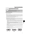
Inverter
Other
equipment
(I) Independent earthing (grounding).......Best
Inverter
Other
equipment
(II) Joint earthing (grounding).......Good
Inverter
Other
equipment
(III) Joint earthing (grounding).......Not allowed