7
SPECIFICATIONS
195
Installation of the heatsink portion
outside the enclosure for use
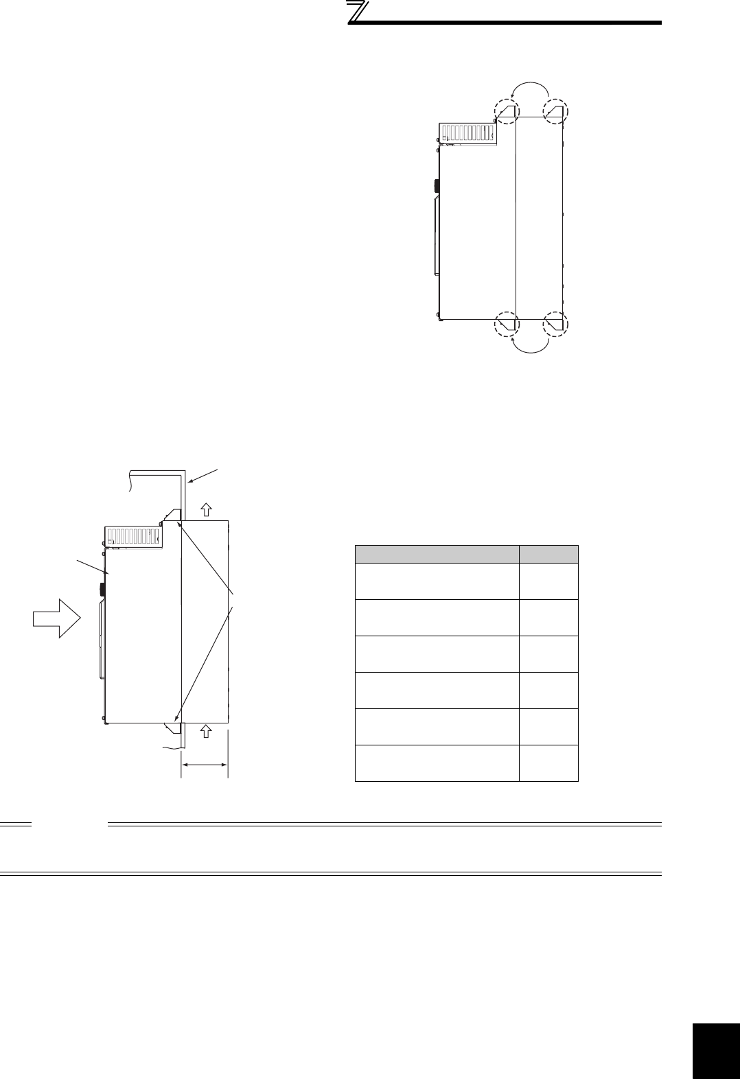
(2) Shift and removal of a rear side installation frame
(3) Installation of the inverter
Push the inverter heatsink portion outside the enclosure and fix the enclosure and inverter with upper and lower
installation frame.
One installation frame is attached to each of the upper and lower
parts of the inverter. Change the position of the rear side
installation frame on the upper and lower sides of the inverter to
the front side as shown on the right. When changing the
installation frames, make sure that the installation orientation is
correct.
CAUTION
· Having a cooling fan, the cooling section which comes out of the enclosure can not be used in the environment of water
drops, oil, mist, dust, etc.
· Be careful not to drop screws, dust etc. into the inverter and cooling fan section.
Upper
installation
frame
Lower
installation
frame
Shift
Shift
Inverter
Inside the
enclosure
Enclosure
Exhausted air
Installation
frame
Dimension of
the outside of
the enclosure
Cooling
wind
D1
(Unit: mm)
Inverter model D1
FR-A721-5.5K, 7.5K
FR-A741-5.5K, 7.5K
100
FR-A721-11K, 15K
FR-A741-11K, 15K
125
FR-A721-18.5K, 22K
FR-A741-18.5K, 22K
130
FR-A721-30K
FR-A741-30K
145
FR-A721-37K, 45K
FR-A741-37K, 45K
163
FR-A721-55K
FR-A741-55K
190


