


155
Causes and corrective actions
5
TROUBLESHOOTING
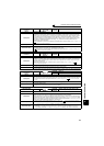
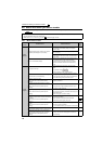
Operation Panel
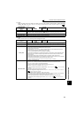
Indication
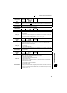
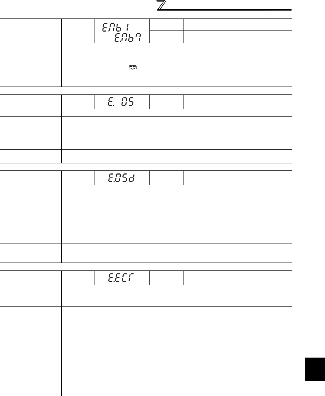
E.MB1 to 7
FR-PU04
⎯⎯
FR-PU07 E.MB1 Fault to E.MB7 Fault
Name
Brake sequence fault
Description
The inverter output is stopped when a sequence error occurs during use of the brake sequence
function (Pr. 278 to Pr. 285). This fault is not available in the initial status (brake sequence function is
invalid). (Refer to Chapter 4 of the Instruction Manual (Applied).)
Check point
Find the cause of alarm occurrence.
Corrective action
Check the set parameters and perform wiring properly.
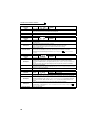
Operation Panel
Indication
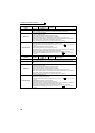
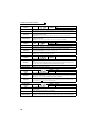
E.OS
FR-PU04
FR-PU07
E. OS
Name
Overspeed occurrence
Description
Stops the inverter output when the motor speed exceeds the Pr. 374 Overspeed detection level during
encoder feedback control Real sensorless vector control and vector control. This fault is not available
in the initial status.
Check point
y Check that the Pr. 374 Overspeed detection level value is correct.
y Check that the number of encoder pulses does not differ from the actual number of encoder pulses.
Corrective action
y Set the Pr. 374 Overspeed detection level value correctly.
y Set the correct number of encoder pulses in Pr. 369 Number of encoder pulses.
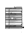
Operation Panel
Indication
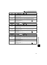
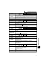
E.OSD
FR-PU04
FR-PU07
E. OSd
Name
Speed deviation excess detection
Description
Stops the inverter output if the motor speed is increased or decreased under the influence of the load
etc. during vector control with Pr. 285 Speed deviation excess detection frequency set and cannot be
controlled in accordance with the speed command value.
This fault is not available in the initial status.
Check point
y Check that the values of Pr. 285 Speed deviation excess detection frequency and Pr. 853 Speed deviation
time are correct.
y Check for sudden load change.
y Check that the number of encoder pulses does not differ from the actual number of encoder pulses.
Corrective action
y Set Pr. 285 Speed deviation excess detection frequency and Pr. 853 Speed deviation time correctly.
y Keep load stable.
y Set the correct number of encoder pulses in Pr. 369 Number of encoder pulses.
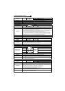
Operation Panel
Indication
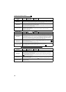
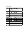
E.ECT
FR-PU04
FR-PU07
E. ECT
Name
Signal loss detection
Description
Trips the inverter when the encoder signal is shut off under orientation control, encoder feedback
control or vector control. This fault is not available in the initial status.
Check point
y Check for the encoder signal loss.
y Check that the encoder specifications are correct.
y Check for a loose connector.
y Check that the switch setting of the FR-A7AP/FR-A7AL (option) is correct.
y Check that the power is supplied to the encoder. Or, check that the power is not supplied to the
encoder later than the inverter.
Corrective action
y Remedy the signal loss.
y Use an encoder that meets the specifications.
y Make connection securely.
y Make a switch setting of the FR-A7AP/FR-A7AL (option) correctly. (Refer to page 29)
y Supply the power to the encoder. Or supply the power to the encoder at the same time when the
power is supplied to the inverter.
If the power is supplied to the encoder after the inverter, check that the encoder signal is securely
sent and set "0" in Pr. 376.
to