


121
Parameter List
Parameter List
4
DRIVING THE MOTOR
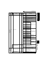
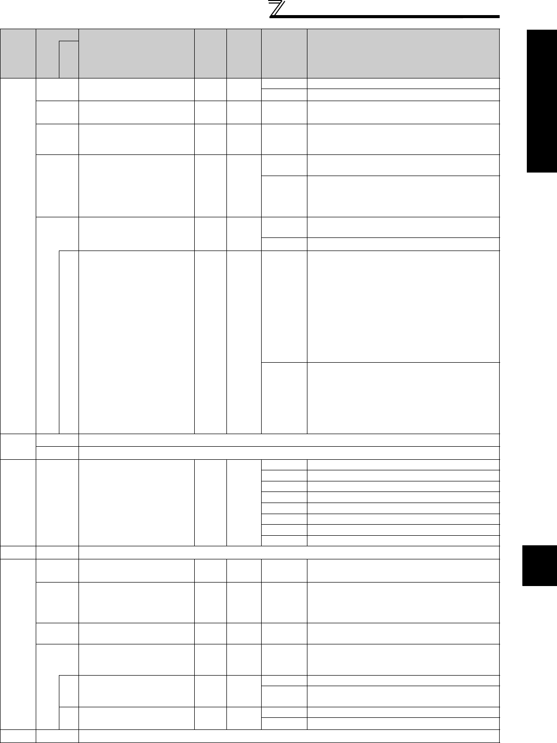
Switch between the inverter operation and
electronic bypass operation to use
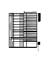
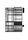
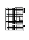
135
Electronic bypass
sequence selection
10
0 Without electronic bypass sequence
1 With electronic bypass sequence
136
MC switchover interlock
time
0.1s 1s 0 to 100s Set the operation interlock time of MC2 and MC3.
137
Start waiting time
0.1s 0.5s 0 to 100s
Set the time slightly longer (0.3 to 0.5s or so) than the
time from when the ON signal enters MC3 until it
actually turns on.
138
Bypass selection at a fault
10
0
Inverter output is stopped (motor coast) at inverter
fault.
1
Operation is automatically switched to bypass
operation at inverter fault
(Not switched when an external thermal relay
operation (E.OHT) or CPU fault (E.CPU) occurs)
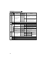
139
Automatic switchover
frequency from inverter to
bypass operation
0.01Hz 9999
0 to 60Hz
Set the frequency to switch inverter operation to
bypass operation.
9999 Without automatic switchover
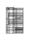
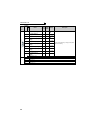
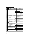
159
Automatic switchover
frequency range from
bypass to inverter operation
0.01Hz 9999
0 to 10Hz
Valid during automatic switchover operation (Pr. 139 ≠
9999)
When the frequency command decreases below (Pr.
139 - Pr. 159) after operation is switched from inverter
operation to bypass operation, the inverter
automatically switches operation to inverter operation
and operates at the frequency of frequency
command.
When the inverter start command (STF/STR) is
turned OFF, operation is switched to inverter
operation also.
9999
Valid during automatic switchover operation (Pr. 139 ≠
9999)
When the inverter start command (STF/STR) is
turned OFF after operation is switched from inverter
operation to bypass operation, operation is switched
to inverter operation and the motor decelerates to
stop.
—
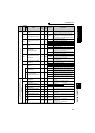
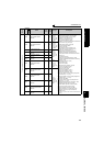
140
to
143
Refer to Pr. 29.
144
Refer to Pr. 37.
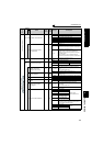
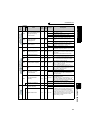
Parameter unit
language switchover
145
PU display language
selection
10
0 Japanese
1 English
2 Germany
3 French
4 Spanish
5 Italian
6 Swedish
7 Finnish
—
148,149
Refer to Pr. 22.
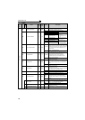
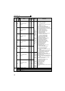
Output current detection (Y12 signal)
Zero current detection (Y13 signal)
150
Output current detection
level
0.1% 150% 0 to 220%
Set the output current detection level.
100% is the rated inverter current.
151
Output current detection
signal delay time
0.1s 0s 0 to 10s
Set the output current detection period.
Set the time from when the output current has risen
above the setting until the output current detection
signal (Y12) is output.
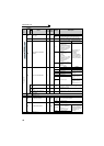
152
Zero current detection level
0.1% 5% 0 to 220%
Set the zero current detection level.
Suppose that the rated inverter current is 100%.
153
Zero current detection time
0.01s 0.5s 0 to 1s
Set this parameter to define the period from when the
output current drops below the Pr. 152 value until the
zero current detection signal (Y13) is output.
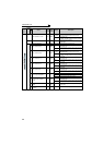
166
Output current detection
signal retention time
0.1s 0.1s
0 to 10s Set the retention time when the Y12 signal is on.
9999
The Y12 signal on status is retained.
The signal is turned OFF at the next start.
167
Output current detection
operation selection
10
0 Operation continues when the Y12 signal is on
1 The inverter trips when the Y12 signal is on. (E.CDO)
—
154
Refer to Pr. 22.
Func
t
ion
Parameter
Name
Incre
ments
Initial
Value
Range Description
Related
parameters