


3
PRECAUTIONS FOR USE OF THE INVERTER
43
Precautions for use of the inverter
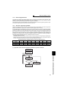
3.4 Precautions for use of the inverter
The FR-A701 series is a highly reliable product, but incorrect peripheral circuit making or operation/handling method
may shorten the product life or damage the product.
Before starting operation, always recheck the following items.
(1) Use crimping terminals with insulation sleeve to wire the power supply and motor.
(2) Application of power to the output terminals (U, V, W) of the inverter will damage the inverter. Never perform
such wiring.
(3) After wiring, wire offcuts must not be left in the inverter.
Wire offcuts can cause an alarm, failure or malfunction. Always keep the inverter clean. When drilling mounting holes in
an enclosure etc., take care not to allow chips and other foreign matter to enter the inverter.
(4) Use cables of the size to make a voltage drop 2% maximum.
If the wiring distance is long between the inverter and motor, a main circuit cable voltage drop will cause the motor torque
to decrease especially at the output of a low frequency.
Refer to page
16 for the recommended cable sizes.
(5) The overall wiring length should be within 500m with unshielded wires (within 100m for the operation under
vector control or when using shielded wires).
Especially for long distance wiring, the fast-response current limit function may decrease or the equipment connected to
the output side may malfunction or become faulty under the influence of a charging current due to the stray capacity of
the wiring. Therefore, note the overall wiring length. (Refer to page 18.)
(6) Electromagnetic wave interference
The input/output (main circuit) of the inverter includes high frequency components, which may interfere with the
communication devices (such as AM radios) used near the inverter. In this case, connecting a capacitor type filter will
reduce electromagnetic wave interference.
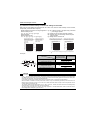
(7) Do not install a power factor correction capacitor, surge suppressor or capacitor type filter on the inverter
output side.
This will cause the inverter to trip or the capacitor, and surge suppressor to be damaged. If any of the above devices is
installed, immediately remove it.
(8) For some short time after the power is switched off, a high voltage remains in the smoothing capacitor.
When accessing the inverter for inspection, wait for at least 10 minutes after the power supply has been switched off, and
then make sure that the voltage across the main circuit terminals P/+-N/- of the inverter is not more than 30VDC using a
tester, etc. The capacitor is charged with high voltage for some time after power off and it is dangerous.
(9) A short circuit or earth (ground) fault on the inverter output side may damage the inverter modules.
· Fully check the insulation resistance of the circuit prior to inverter operation since repeated short circuits caused by
peripheral circuit inadequacy or an earth (ground) fault caused by wiring inadequacy or reduced motor insulation
resistance may damage the inverter modules.
· Fully check the to-earth (ground) insulation and inter-phase insulation of the inverter output side before power-on.
Especially for an old motor or use in hostile atmosphere, securely check the motor insulation resistance etc.
(10) Do not use the inverter input side magnetic contactor to start/stop the inverter.
Since repeated inrush currents at power ON will shorten the life of the converter circuit (switching life is about 500,000
times), frequent starts and stops of the MC must be avoided.
Always use the start signal (ON/OFF of STF and STR signals) to start/stop the inverter.
(11) Do not apply a voltage higher than the permissible voltage to the inverter I/O signal circuits.
Application of permissible voltage to the inverter I/O signal circuit and incorrect polarity may damage the I/O terminal.
Especially check the wiring to prevent the speed setting potentiometer from being connected incorrectly to short
terminals 10E-5.
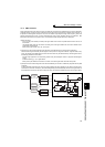
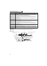
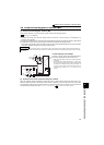
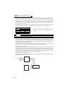
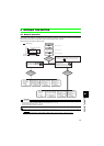
(12) Provide electrical and mechanical interlocks for MC1
and MC2 which are used for bypass operation.
When the wiring is incorrect or if there is an electronic
bypass circuit as shown on the right, the inverter will be
damaged by leakage current from the power supply due to
arcs generated at the time of switch-over or chattering
caused by a sequence error.
(Commercial operation can not be performed with the vector
dedicated motor (SF-V5RU, SF-THY).)
(Refer to page
12)
Power
supply
Inverter
Undesirable current
MC2
MC1
Interlock
U
V
W
R/L1
S/L2
T/L3
IM