


173
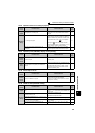
Inspection item
6
PRECAUTIONS FOR MAINTENANCE AND INSPECTION
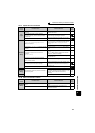
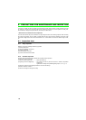
(2) Measuring method of life of the main circuit capacitor
·
If the value of capacitor capacity measured before shipment is considered as 100%, Pr. 255 bit1 is turned ON when
the measured value falls below 85%.
· Measure the capacitor capacity according to the following procedure and check the deterioration level of the
capacitor capacity.
1) Check that the motor is connected and at a stop.
2) Set "1" (measuring start) in Pr. 259
3) Switch power off. The inverter applies DC voltage to the motor to measure the capacitor capacity while the inverter is off.
4) After confirming that the LED of the operation panel is off, power on again.
5) Check that "3" (measuring completion) is set in Pr. 259, then read Pr .258 and check the life of the main circuit capacitor.
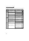
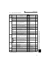
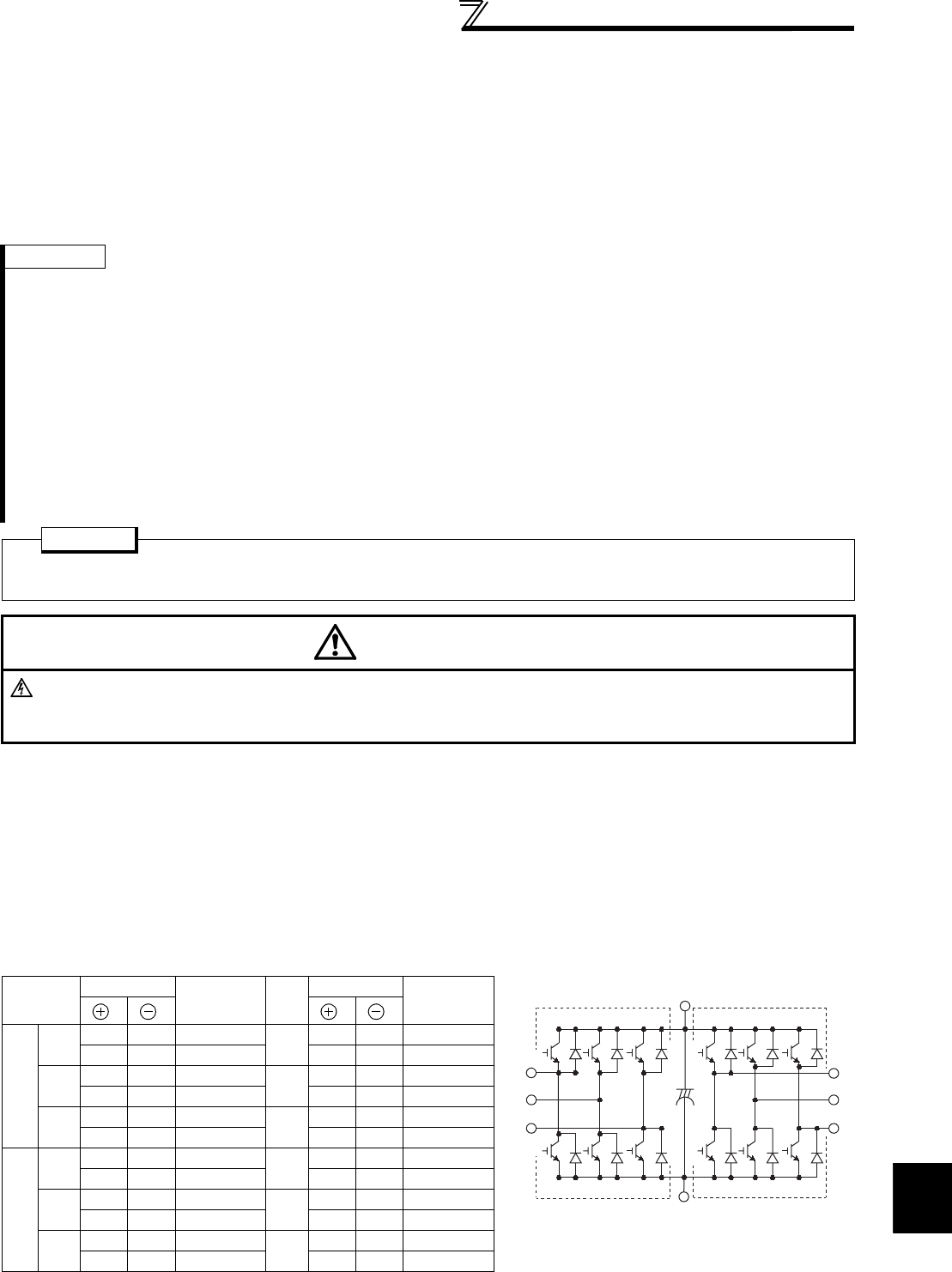
6.1.5 Checking the inverter and converter modules
<Preparation>
(1) Disconnect the external power supply cables (R/L1, S/L2, T/L3) and motor cables (U, V, W).
(2) Prepare a tester. (Use 100Ω range.)
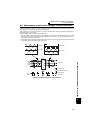
<Checking method>
Change the polarity of the tester alternately at the inverter terminals R/L1, S/L2, T/L3, U, V, W, P/+ and N/−, and check
for electric continuity.
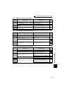
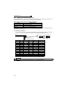
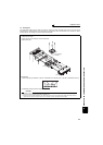
<Module device numbers and terminals to be checked>
(Assumes the use of an analog meter.)
REMARKS
· When the main circuit capacitor life is measured under the following conditions, "forced end" (Pr. 259 = "8") or "measuring error"
(Pr. 259 = "9") occurs or it remains in "measuring start" (Pr. 259 = "1"). When measuring, avoid the following conditions to
perform.
In addition, even when "measurement completion" (Pr. 259 = "3") is confirmed under the following conditions, normal
measurement can not be done.
(a)Terminal R1/L11, S1/L21 is connected to the terminals P/+ and N/−.
(b)Switch power on during measuring.
(c)The motor is not connected to the inverter.
(d)The motor is running.(The motor is coasting.)
(e)The motor capacity is two rank smaller as compared to the inverter capacity.
(f)The inverter is at an alarm stop or an alarm occurred while power is off.
(g)The inverter output is shut off with the MRS signal.
(h)The start command is given while measuring.
· Operating environment: Surrounding air temperature (annual average 40
°
C (free from corrosive gas, flammable gas, oil mist, dust
and dirt))
Output current (80% of the inverter rated current)
POINT
For accurate life measurement of the main circuit capacitor, wait 3 hours or longer after turning OFF. The
temperature left in the main circuit capacitor affects measurement.
WARNING
When measuring the main circuit capacitor capacity (Pr. 259 Main circuit capacitor life measuring = "1"), the DC
voltage is applied to the motor for 1s at powering off. Never touch the motor terminal, etc. right after powering off
to prevent an electric shock.
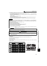
Tester Polarity
Measured
Value
Tester Polarity
Measured
Value
Converter
module
TR11
R/L1 P/+ Discontinuity
TR14
R/L1 N/− Continuity
P/+ R/L1 Continuity N/− R/L1 Discontinuity
TR13
S/L2 P/+ Discontinuity
TR16
S/L2 N/− Continuity
P/+ S/L2 Continuity N/− S/L2 Discontinuity
TR15
T/L3 P/+ Discontinuity
TR12
T/L3 N/− Continuity
P/+ T/L3 Continuity N/− T/L3 Discontinuity
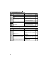
Inverter
module
TR1
UP/+ Discontinuity
TR4
UN/− Continuity
P/+ U Continuity N/− U Discontinuity
TR3
VP/+ Discontinuity
TR6
VN/− Continuity
P/+ V Continuity N/− V Discontinuity
TR5
WP/+ Discontinuity
TR2
WN/− Continuity
P/+ W Continuity N/− W Discontinuity
Converter module Inverter module
U
V
W
R/L1
S/L2
T/L3
P/+
N/−
TR1 TR3 TR5
TR4 TR6 TR2
C
TR11 TR13 TR15
TR14 TR16 TR12