


201
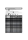
*1 These instruction codes are used for parameter read and write by using Mitsubishi inverter protocol with the RS-485 communication.
(Refer to
Chapter 4 of the Instruction Manual (Applied) for RS-485 communication)
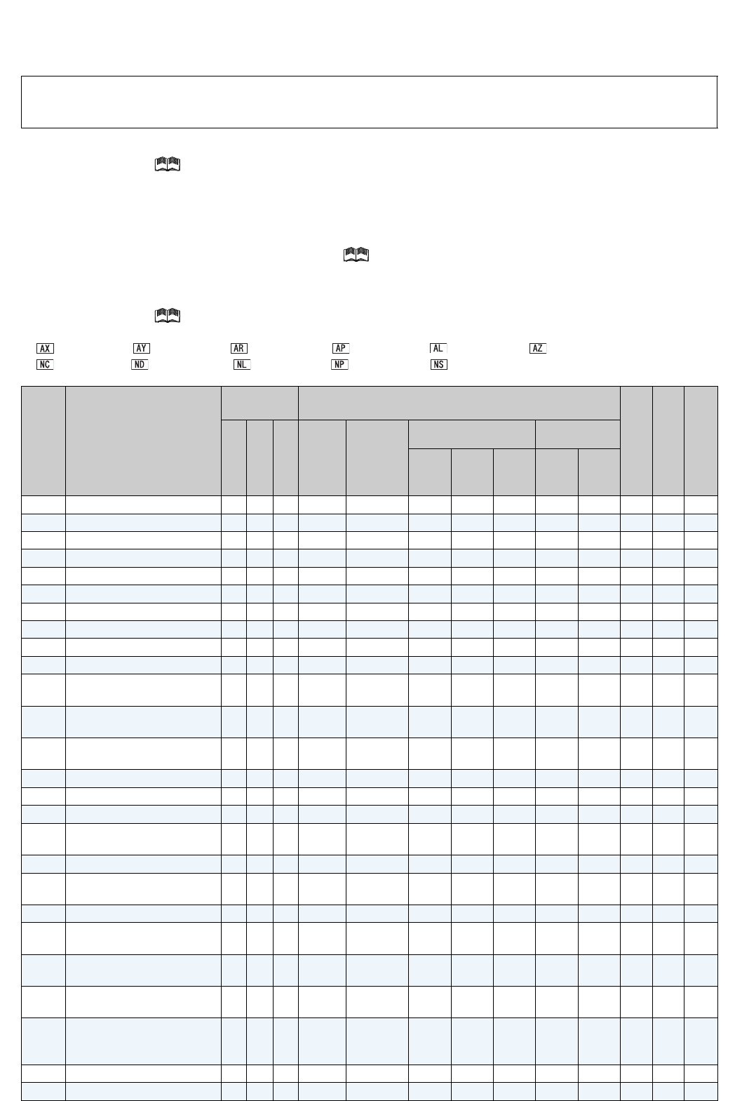
*2 Validity and invalidity according to operation mode are as follows:
{:Usable parameter
×:Unusable parameter
Δ:Parameters available only during position control set by parameter
*3 "{" indicates valid and "
×" indicates invalid of "parameter copy", "parameter clear", and "all parameter clear".
*4 Parameters can be used with conditions. Refer to
Chapter 4 of the Instruction Manual (Applied) for details.
*5 When a communication option is installed, parameter clear (lock release) during password lock (Pr. 297 ≠ 9999) can be performed only from the
communication option.
*6 These parameters are communication parameters that are not cleared when parameter clear (all clear) is executed from RS-485 communication.
(Refer to
Chapter 4 of the Instruction Manual (Applied) for RS-485 communication)
Symbols in the table indicate parameters which function when an option is mounted.
........ FR-A7AX, ......... FR-A7AY, ......... FR-A7AR, ........ FR-A7AP, ......... FR-A7AL, ......... FR-A7AZ,
........ FR-A7NC, ......... FR-A7ND, ........ FR-A7NL, ......... FR-A7NP, ......... FR-A7NS
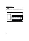
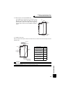
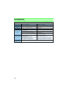
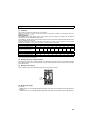
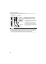
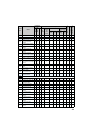
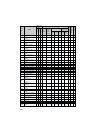
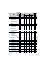
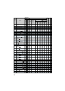
Appendix 4 Control mode-based parameter (function) correspondence
table and instruction code list
Param
eter
Name
Instruction
Code
* 1
Control Mode-based Correspondence Table *2
Parameter Copy
*3
Parameter Clear
*3
All Parameter Clear
*3
Read
Write
Extended
V/F
Control
Advanced
magnetic
flux
vector
control
Vector control
Real sensorless
vector control
Speed
control
Torque
control
Position
control
Speed
control
Torque
control
0
Torque boost
00 80 0
{
× ×××××
{{{
1
Maximum frequency
01 81 0
{ { { { { { { { { {
2
Minimum frequency
02 82 0
{{{{
×
{{{{{
3
Base frequency
03 83 0
{
× × × × × ×
{ { {
4
Multi-speed setting (high speed)
04 84 0
{{{{Δ {{{{{
5
Multi-speed setting (middle speed)
05 85 0
{ { { { Δ { { { { {
6
Multi-speed setting (low speed)
06 86 0
{{{{
Δ
{{{{{
7
Acceleration time
07 87 0
{ { { {
Δ
{ { { { {
8
Deceleration time
08 88 0
{{{{
Δ
{{{{{
9
Electronic thermal O/L relay
09 89 0
{ { { { { { { { { {
10
DC injection brake operation
frequency
0A 8A 0
{{{{
×
{{{{{
11
DC injection brake operation
time
0B 8B 0
{ { { { × { { { { {
12
DC injection brake operation
voltage
0C 8C 0
{{×××
{
*4
{
*4
{{{
13
Starting frequency
0D 8D 0
{ { { {
×
{ { { { {
14
Load pattern selection
0E 8E 0
{
× ×××××
{{{
15
Jog frequency
0F 8F 0
{ { { {
×
{ { { { {
16
Jog acceleration/
deceleration time
10 90 0
{{{{
×
{{{{{
17
MRS input selection
11 91 0
{ { { { { { { { { {
18
High speed maximum
frequency
12 92 0
{{
×××××
{{{
19
Base frequency voltage
13 93 0
{
× × × × × ×
{ { {
20
Acceleration/deceleration
reference frequency
14 94 0
{{{{
Δ
{{{{{
21
Acceleration/deceleration
time increments
15 95 0
{ { { { Δ { { { { {
22
Stall prevention operation
level (Torque limit level )
16 96 0
{{{× {{× {{{
23
Stall prevention operation
level compensation factor at
double speed
17 97 0
{ { × × × × × { { {
24
Multi-speed setting (speed 4)
18 98 0
{{{{
Δ
{{{{{
25
Multi-speed setting (speed 5)
19 99 0
{ { { { Δ { { { { {