


131
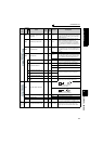
Parameter List
Parameter List
4
DRIVING THE MOTOR
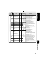
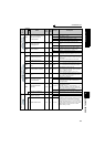
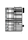
Orientation control
363
Completion signal output
delay time
0.1s 0.5s 0 to 5s
The orientation complete signal (ORA) is output
delaying the set time after in-position zone is entered.
Also, the signal turns off delaying the set time after
in-position zone is out.
364
Encoder stop check time
0.1s 0.5s 0 to 5s
Orientation fault signal (ORM) is output when the
encoder remains stopped for the set time without
orientation completion in the state where no
orientation complete signal (ORA) is output. ORM
signal is output when orientation is not completed
again in the set time in the state where ORA signal is
output.
365
Orientation limit
1s 9999
0 to 60s
Measure the time taken after passing the creep
switchover position and output the orientation fault
signal (ORM) if orientation is not completed within the
set time.
9999 Set to 120s.
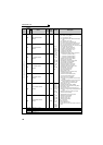
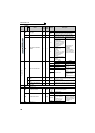
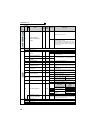
366
Recheck time
0.1s 9999
0 to 5s
Turning off the start signal with orientation command
(X22) on after stopping the motor by orientation
control, the present position is checked again after the
set time elapses and the orientation complete signal
(ORA) or orientation fault signal (ORM) is output.
9999 Not checked.
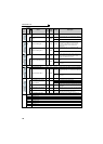
369
Number of encoder pulses
1 1024 0 to 4096
Set the number of pulses of the encoder.
Set the number of pulses before multiplied by four.
393
Orientation selection
10
0
Orientation is executed from the current rotation
direction.
1
Orientation is executed from the forward rotation
direction.
2
Orientation is executed from the reverse rotation
direction.
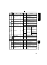
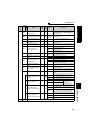
396
Orientation speed gain (P
term)
1 60 0 to 1000
Servo rigidity is (response level during position
control loop) at orientation stop can be adjusted.
397
Orientation speed integral
time
0.001s 0.333s 0 to 20.0s
398
Orientation speed gain (D
term)
0.1% 1%
0 to 100.0%
Lag/advance compensation gain can be adjusted.
399
Orientation deceleration
ratio
1 20 0 to 1000
Make adjustment when the motor runs back at
orientation stop or the orientation time is long.
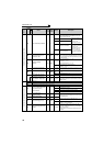
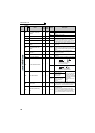
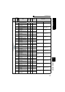
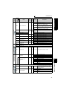
Encoder feedback control
359
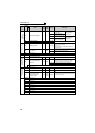
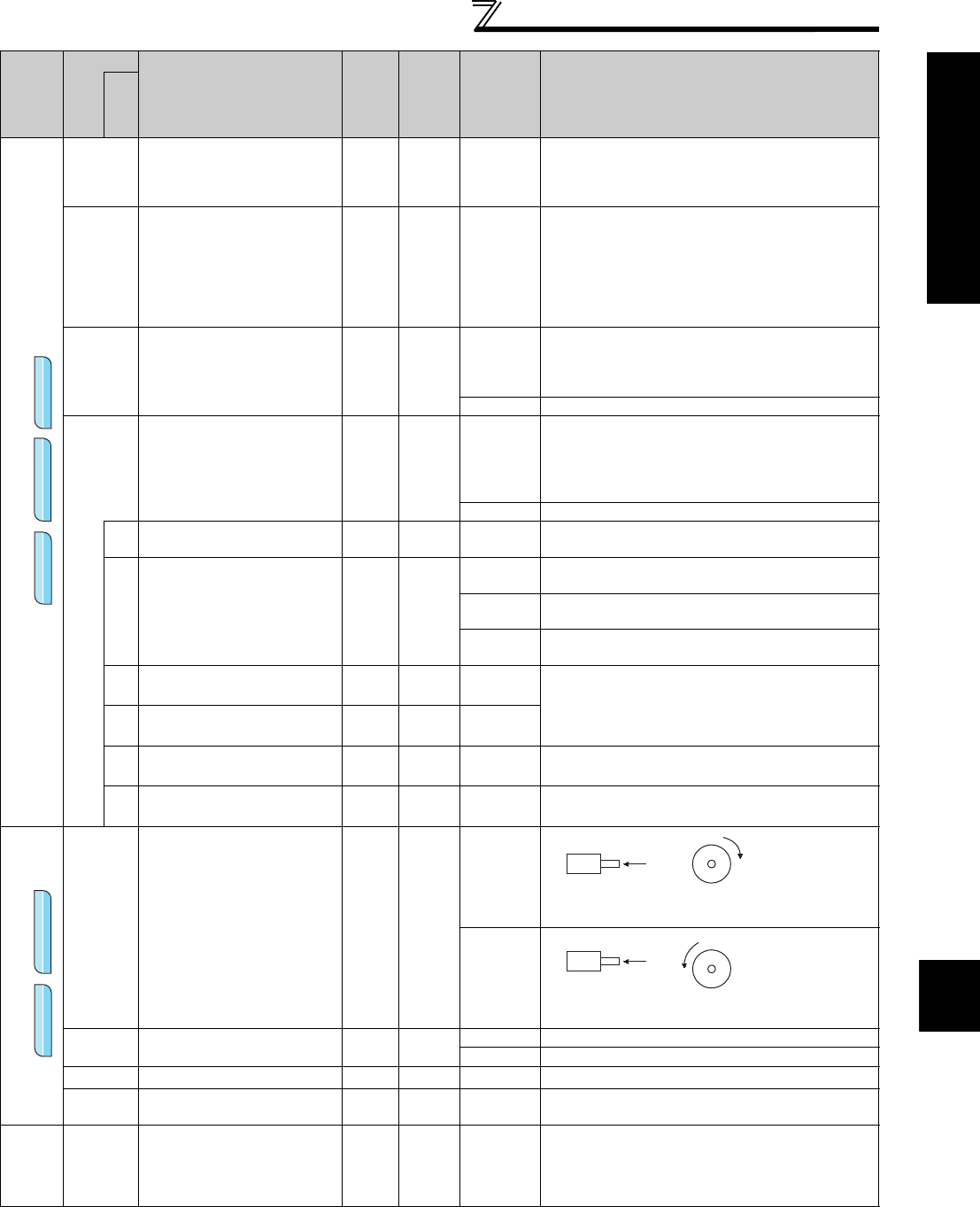
Encoder rotation direction
11
0
1
367
Speed feedback range
0.01Hz 9999
0 to 400Hz Set the range of speed feedback control.
9999 Encoder feedback control is invalid
368
Feedback gain
0.1 1 0 to 100 Set when the rotation is unstable or response is slow.
369
Number of encoder pulses
1 1024 0 to 4096
Set the number of pulses of the encoder.
Set the number of pulses before multiplied by four.
Overspeed
detection
374
Overspeed detection level
0.01Hz 140Hz 0 to 400Hz
When the motor speed reaches or exceeds the speed
set in
Pr.374
during encoder feedback control, Real
sensorless vector control, or vector control, over
speed (E.OS) occurs and stops the inverter output.
Func
t
ion
Parameter
Name
Incre
ments
Initial
Value
Range Description
Related
parameters
V/F
V/F
V/F
Magnetic flux
Magnetic flux
Magnetic flux
Vector
Vector
Vector
V/F
V/F
V/F
Magnetic flux
Magnetic flux
Magnetic flux
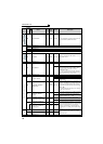
A
Encoder
CW
Clockwise direction as viewed
from A is forward rotation
CCW
A
Encoder
Counter clockwise direction as
viewed from A is forward rotation