


2/4 BCN-C22005-646
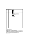
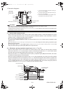
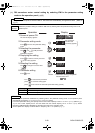
<Connection diagram>
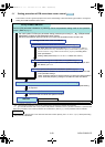
(1) Set the brake sequence mode
Select either Real sensorless vector control, vector control (speed control) or Advanced magnetic flux vector
control. The brake sequence function is valid only when the External operation mode, External/PU combined
operation mode 1 or Network operation mode is selected.
Set "7(17) or 8(18)" (brake sequence mode) in Pr.292.
To ensure more complete sequence control, it is recommended to set "7(17)" (brake opening completion signal
input) in Pr.292.
Set "15" in any of Pr.178 to Pr.189 (input terminal function selection) and assign the brake opening completion signal
(BRI) to the input terminal.
Set "20 (positive logic)" or "120 (negative logic)" in any of Pr.190 to Pr.196 (output terminal function selection) and
assign the brake opening request signal (BOF) to the output terminal.
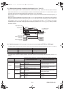
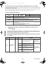
(2) With brake opening completion signal input (Pr.292 = "7 or 17")
When the start signal is input to the inverter, the inverter starts running. When the internal speed command
reaches the value set in Pr.278 and the output current is not less than the value set in Pr.279, the inverter outputs
the brake opening request signal (BOF) after the time set in Pr.280 has elapsed.
When the time set in Pr.281 elapses after the brake opening completion signal (BRI) was activated, the inverter
increases the output frequency to the set speed.
When the inverter decelerates to the frequency set in Pr.282 during deceleration, the inverter turns OFF the BOF
signal and decelerates further to the frequency set in Pr.278. After electromagnetic brake operation completes and
inverter recognizes the turn OFF of BRI signal, the inverter holds the frequency set in Pr.278 for the time set in
Pr.283. And after the time set in Pr.283 passes, the inverter decelerates again. The inverter finally stops when its
frequency reaches to Pr.13 Starting frequency setting or 0.5Hz, whichever is lower.
CAUTION
When brake sequence mode is selected, automatic restart after instantaneous power failure is invalid.
When using this function, set the acceleration time to 1s or longer.
Changing the terminal function using any of Pr.178 to Pr.189, Pr.190 to Pr.196 may affect the other functions. Set parameters after
confirming the function of each terminal.
Mechanical
brake
R/L1
S/L2
T/L3
Motor
MC
STF
RH
AU(BRI) *1
SD
MC
24VDC
Brake opening request
signal (BOF)
Start signal
Multi-speed signal
Brake opening completion signal
(BRI)
Sink logic
Pr.184 = 15
Pr.190 = 20
Power
supply
U
V
W
RUN(BOF)
SE
*2
*3
MCCB
*1 The input signal terminal used differs according to
the Pr.178 to Pr.189 settings.
*2 The output signal terminal used differs according to
the Pr.190 to Pr.196 settings.
*3 The current should be within the permissible current
of transistor in the inverter. (24V 0.1ADC)
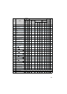
Time
ON
Pr.280
Pr.281
Pr.283
Pr.279
ON
Opened
Closed Closed
ON
STF
Output current
Brake opening request
(BOF signal)
Brake opening completion
(BRI signal)
Pr.278
Pr.282
Target frequency
Pr.13
Output frequency(Hz)
Electromagnetic brake
operation
Pr.13 setting or 0.5Hz,
whichever is lower
bcnc22005646.fm 2 ページ 2013年9月9日 月曜日 午後12時49分