


2
WIRING
15
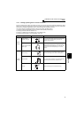
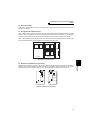
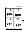
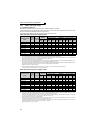
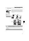
Main circuit terminal specifications
400V class
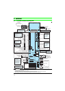
FR-A741-5.5K, 7.5K FR-A741-11K, 15K
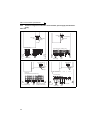
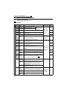
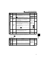
FR-A741-18.5K to 45K FR-A741-55K
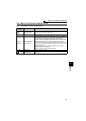
CAUTION
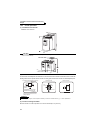
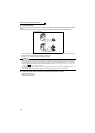
· The power supply cables must be connected to R/L1, S/L2, T/L3. (Phase sequence needs not to be matched.) Never connect
the power cable to the U, V, W of the inverter. Doing so will damage the inverter.
· Connect the motor to U, V, W. At this time, turning ON the forward rotation switch (signal) rotates the motor in the
counterclockwise direction when viewed from the motor shaft.
IM
Motor
Power supply
R/L1 S/L2 T/L3
N/-
P/+
Jumper
Charge lamp
Screw size (M4)
R1/L11
S1/L21
Screw size (M4)
IM
R/L1 S/L2 T/L3
N/-
P/+
S1/L21
R1/L11
Motor
Power supply
Jumper
Charge lamp
Screw size (M4)
Screw size (M5)
IM
R/L1 S/L2 T/L3
N/-
P/+
Screw size (M4)
S1/L21
R1/L11
Charge lamp
Jumper
Motor
Power supply
Screw size (M6 for 18.5K to 30K
M8 for 37K and 45K)
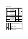
IM
R/L1 S/L2 T/L3
N/-
P/+
S1/L21
R1/L11
Screw size (M4)
Charge lamp
Jumper
Screw size (M8)
Power supply
Motor