


PARAMETERS
103
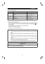
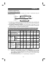
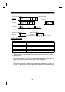
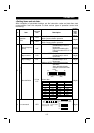
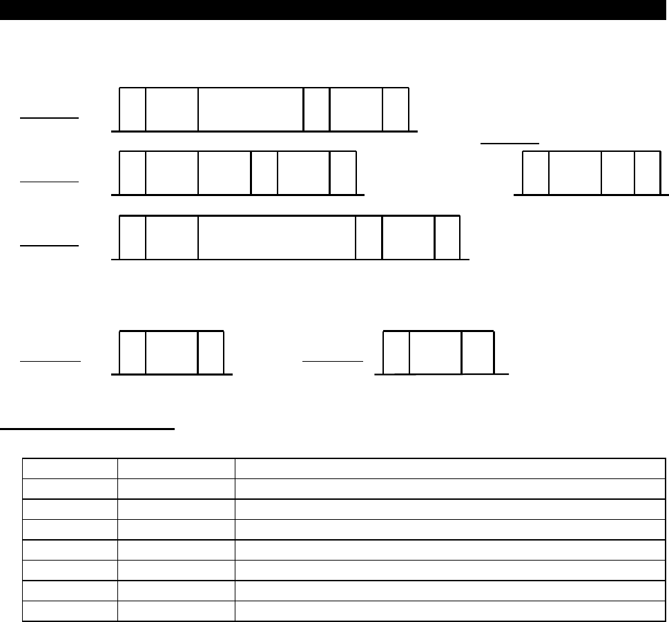
3) Reply data from inverter to computer during data read
Format F
Format E
*
3
NAK
123 4
*
4
5
*
3
STX
*
4
1234567891011
*
3
ETX
*
3
STX
*
4
123456789
*
3
ETX
*
3
STX
*
4
123456789
*
3
ETX
10 11 12 13
[No data error detected]
Inverter
station
number
Inverter
station
number
Read
data
Sum
check
Read
data
Sum
check
Inverter
station
number
Read
data
Sum
check
Format E"
Inverter
station
number
Format E'
[Data error detected]
Error
code
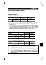
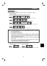
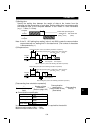
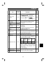
4) Send data from computer to inverter during data read
Format G
[No data error detected]
*
3
ACK
*
4
1234
Inverter
station
number
←
Number of characters
Format H
[Data error detected]
*
3
NAK
123 4
*
4
Inverter
station
number
←
Number of characters
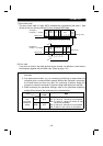
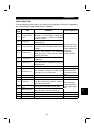
(4) Data definitions
1) Control codes
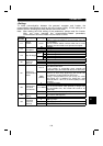
Signal ASCII Code Description
STX H02 Start of Text (Start of data)
ETX H03 End of Text (End of data)
ENQ H05 Enquiry (Communication request)
ACK H06 Acknowledge (No data error detected)
LF H0A Line Feed
CR H0D Carriage Return
NAK H15 Negative Acknowledge (Data error detected)
2) Inverter station number
Specify the station number of the inverter which communicates with the computer.
3) Instruction code
Specify the processing request, e.g. operation, monitoring, given by the computer
to the inverter. Hence, the inverter can be run and monitored in various ways by
specifying the instruction code as appropriate. (Refer to page 185.)
4) Data
Indicates the data such as frequency and parameters transferred to and from the
inverter. The definitions and ranges of set data are determined in accordance with
the instruction codes. (Refer to page 185.)