


INSTALLATION AND WIRING
12
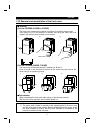
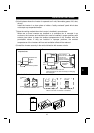
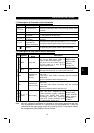
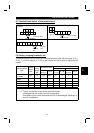
(1) Description of the main circuit terminals
Symbol Terminal Name Description
R, S, T
(L
1
, L
2
, L
3
)
AC power input
Connect to the commercial power supply. Keep these
terminals unconnected when using the high power factor
converter.
U, V, W Inverter output Connect a three-phase squirrel-cage motor.
P (+), PR
Brake resistor
connection
Connect the optional brake resistor across terminals P-PR
(+ - PR) (not for 0.1K and 0.2K).
P (+), N (
−
)
Brake unit
connection
Connect the optional brake unit or high power factor
converter.
P (+), P1
Power factor
improving DC
reactor connection
Disconnect the jumper from terminals P-P1 (+ - P1) and
connect the optional power factor improving DC reactor.
Ground For grounding the inverter chassis. Must be earthed.
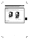
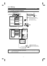
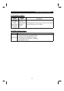
(2) Description of the control circuit terminals
Type Symbol
Terminal
Name
Description
MRS Output halt
Turn on the MRS signal (20ms or
longer) to stop the inverter output.
Used to shut off the inverter output to
bring the motor to a stop by the
electromagnetic brake.
Setting of Pr. 183
"MRS terminal
(MRS) function
selection"
changes the
terminal function.
Contact input
RES Reset
Used to reset the protective circuit activated. Turn on the
RES signal for more than 0.1 second, then turn it off.
P24
Contact input
common
(source)
Common terminal for contact inputs for use in the source
input mode.
In the source input mode, connection with this terminal
switches the
signal on and disconnection switches it off.
Input signals
SD
Contact input
common (sink)
Common terminal for contact inputs for use in the sink
input mode.
In the sink input mode, connection with this terminal
switches the
signal on and disconnection switches it off.
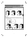
Output signals
Contact
A, B, C
(note)
Alarm output
Contact output indicating that the
output has been stopped by the
inverter protective function activated.
230VAC 0.3A, 30VDC 0.3A. Alarm:
discontinuity across B-C (continuity
across A-C), normal: continuity across
B-C (discontinuity across A-C).
Pr. 192 "A, B, C
terminal (ABC)
function selection"
setting, changes
the terminal
functions.
Note : Wire the cables for application of voltages to the contact outputs so that they
may be separated from the PLC power at the no-fuse breaker etc. If they are
connected to the same power supply as is used by the PLC, the inverter cannot
be changed during DeviceNet
TM
communication.
2