


INSTALLATION AND WIRING
18
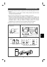
2.2.3 Wiring of the control circuit
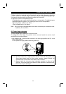
(1) Wiring instructions
1) Terminals SD and P24 are common to the I/O signals.
Do not connect these common terminals together or do not earth these terminals to
the ground.
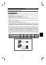
2) Use shielded or twisted cables for connection to the control circuit terminals and run
them away from the main and power circuits (including the 200V relay sequence
circuit).
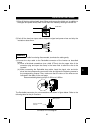
3) The frequency input signals to the control circuit are micro currents. When contacts
are required, use two or more parallel micro signal contacts or a twin contact to
prevent a contact fault.
4) It is recommended to use the cables of 0.3mm
2
to 0.75mm
2
gauge for connection to
the control circuit terminals.
5) When bar terminals and solid wires are used for wiring, their diameters should be
0.9mm maximum. If they are larger, screw threads may be damaged during
tightening.
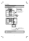
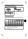
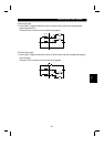
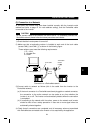
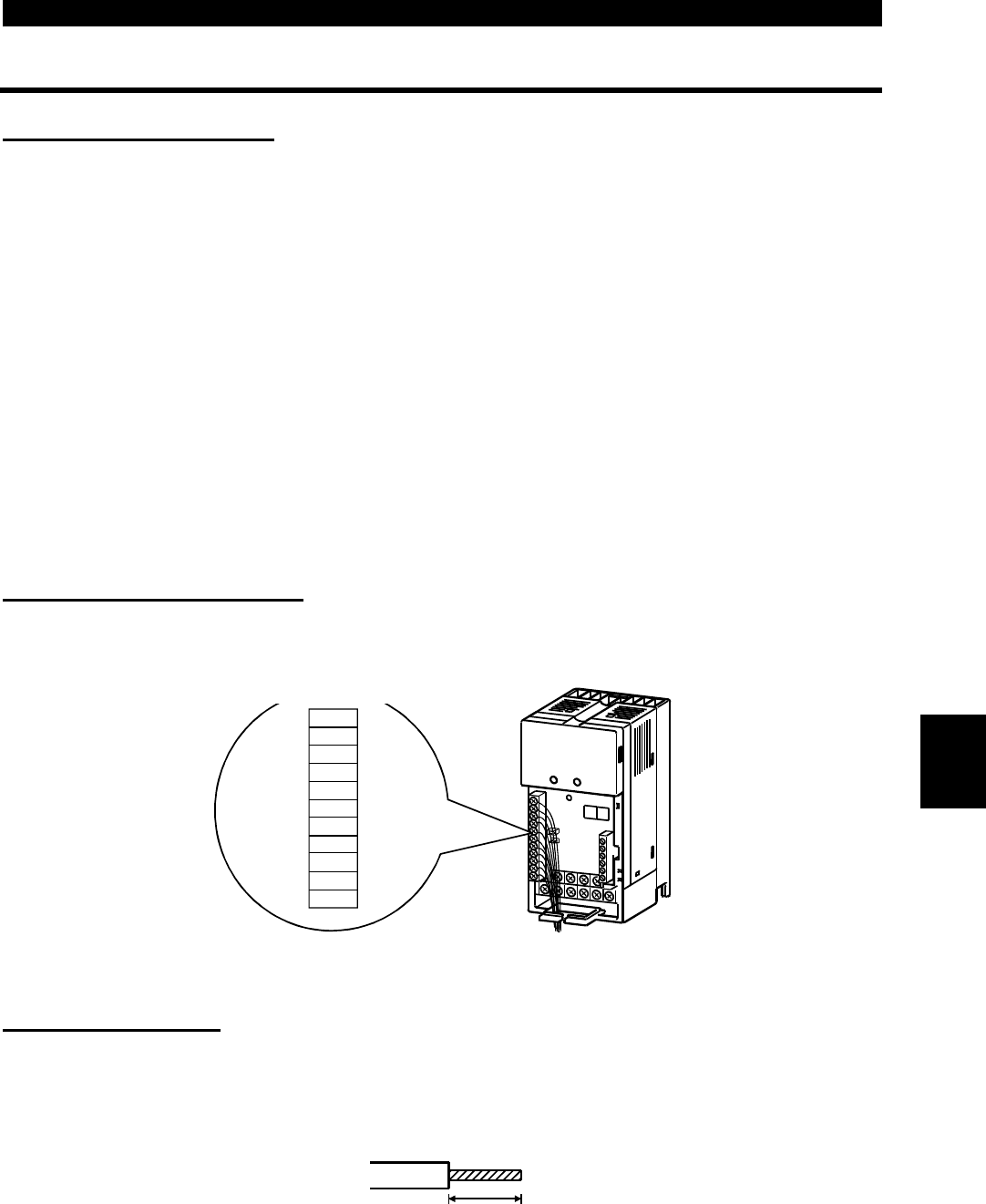
(2) Terminal block layout
In the control circuit of the inverter, the terminals are arranged as shown below:
Terminal layout of
control circuit
P24
P24
SD
SD
MRS
RES
NC
NC
A
B
C
*
*
*: Keep NC unconnected.
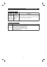
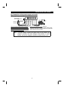
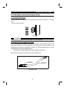
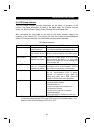
(3) Wiring method
1) For wiring the control circuit, use cables after stripping their sheaths.
Refer to the gauge printed on the inverter and strip the sheaths to the following
dimensions. If the sheath is stripped too much, its cable may be shorted with the
adjoining cable. If the sheath is stripped too little, the cable may come off.
7mm
±
1mm
2