


INSTALLATION AND WIRING
22
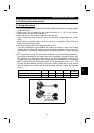
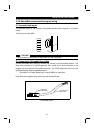
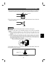
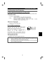
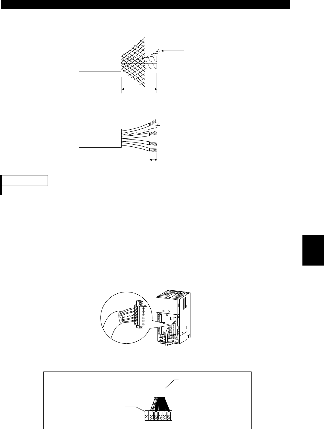
1) Strip off the drop cable sheath about 38mm and remove the shield net. In addition to
the signal and power wires, there is one drain wire made by twisting the shield net.
About 38mm
Drain wire
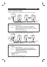
2) Peel off the aluminum tapes which wraps the signal and power wires and strip the
insulations about 6mm.
About 6mm
REMARKS
To prevent the cable from being disconnected, terminate the cable gently.
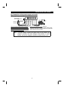
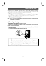
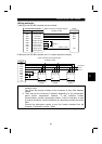
3) Connect the drop cable to the DeviceNet connector of the inverter as described
below.
(a) Insert a flat-blade screwdriver (max. width 3.75mm) into the upper hole of the
connector plug and open the clamp in the lower hole to allow the wire to be
inserted.
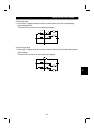
(b) When connecting the DeviceNet drop cable, insert the signal, wire and drain
wires into the corresponding connector holes and tighten the fastening screws to
the corresponding torques. Also, make sure that the colors of the wires are as
indicated in the table on the next page.
Recommended tightening torque: 0.22N
⋅
m to 0.25N
⋅
m
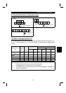
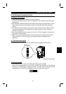
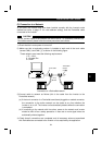
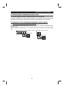
The DeviceNet connector pin out connections are shown in figure below. Refer to the
following table for the pin functions.
V- C- SHC+ V+
Inverter's DeviceNet
connector
DeviceNet Thin
Drop Cable
NC
Connector Pin Out diagram
2