


PROTECTIVE FUNCTIONS
144
"
""
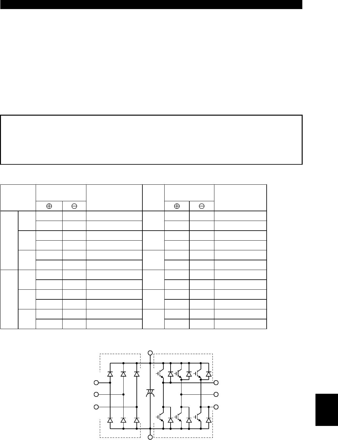
" Checking the inverter and converter modules
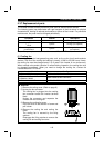
<Preparation>
(1)Disconnect the external power supply cables (R, S, T (L
1
, L
2
, L
3
)) and motor cables
(U, V, W).
(2)Prepare a meter. (Use 100
Ω
range.)
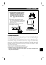
<Checking method>
Change the polarity of the meter alternately at the inverter terminals R (L
1
), S (L
2
),
T (L
3
), U, V, W, P (+) and N (
−
), and check for continuity.
Note:1. Before measurement, check that the smoothing capacitor is discharged.
2. At the time of continuity, the measured value is several to several ten's-of
ohms depending on the number of modules, number of parallel modules,
circuit tester type, etc. If all measured values are almost the same, the
modules are without fault.
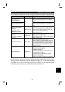
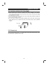
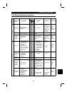
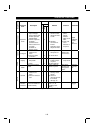
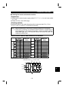
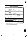
<Module device numbers and terminals to be checked>
Tester
Polarity
Tester
Polarity
Measured
Value
Measured
Value
R (L
1
) P (+) Discontinuity R (L
1
)N (
−
) Continuity
D1
P (+) R (L
1
) Continuity
D4
N (
−
)R (L
1
) Discontinuity
S (L
2
) P (+) Discontinuity S (L
2
)N (
−
) Continuity
D2
P (+) S (L
2
) Continuity
D5
N (
−
)S (L
2
) Discontinuity
T (L
3
) P (+) Discontinuity T (L
3
)N (
−
) Continuity
Converter
module
D3
P (+) T (L
3
) Continuity
D6
N (
−
)T (L
3
) Discontinuity
U P (+) Discontinuity U N (
−
) Continuity
TR1
P (+) U Continuity
TR4
N (
−
) U Discontinuity
V P (+) Discontinuity V N (
−
) Continuity
TR3
P (+) V Continuity
TR6
N (
−
) V Discontinuity
W P (+) Discontinuity W N (
−
) Continuity
Inverter module
TR5
P (+) W Continuity
TR2
N (
−
) W Discontinuity
(Assumes the use of an analog meter.)
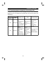
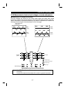
Converter module
Inverter module
D1 D2 D3
D4
D5 D6
TR1 TR3 TR5
TR4 TR6 TR2
U
V
W
R (L
1
)
S (L
2
)
T (L
3
)
C
P (+)
N (-)
5