


INSTALLATION AND WIRING
26
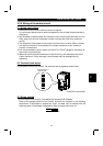
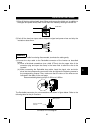
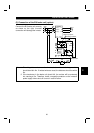
2.2.5 Connection to the PU connector
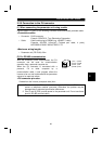
(1) When connecting the parameter unit using a cable
Use the option FR-CB2
#
or the following connector and commercially available cable:
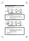
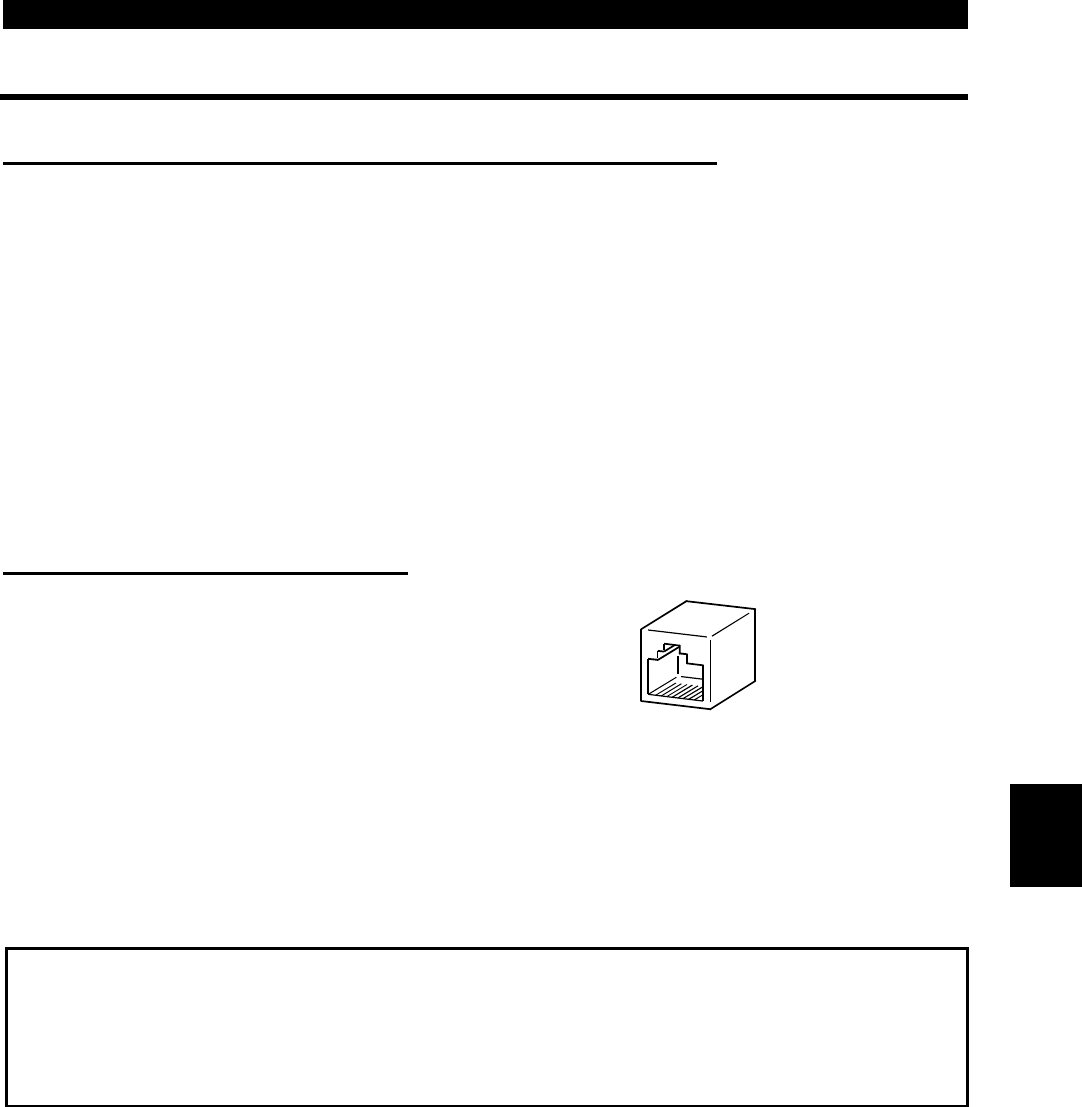
<Connection cable>
!
Connector : RJ45 connector
Exampl: 5-554720-3, Tyco Electronics Corporation
!
Cable : Cable conforming to EIA568 (e.g. 10BASE-T cable)
Example: SGLPEV 0.5mm
×
4P (Twisted pair cable, 4 pairs),
MITSUBISHI CABLE INDUSTRIES, LTD.
<Maximum wiring length>
!
Parameter unit (FR-PU04): 20m
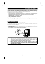
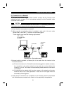
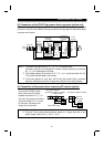
(2) For RS-485 communication
With the accessory cover disconnected, the PU
connector can be used for communication
operation from a personal computer etc.
When the PU connector is connected with a
personal, FA or other computer by a
communication cable, a user program allows the
inverter to be run and monitored and the parameter
values to be read and written.
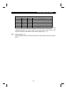
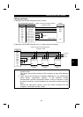
<PU connector pin-outs>
Viewed from the inverter (receptacle side) front
8) to 1)
1) SG
2) P5S
3) RDA
4) SDB
5) SDA
6) RDB
7) SG
8) P5S
Note:1. Do not connect the PU connector to a computer's LAN board, FAX modem
socket or telephone modular connector. Otherwise, the product may be
damaged due to electrical specification differences.
2. Pins 2) and 8) (P5S) provide power to the parameter unit. Do not use these
pins for RS-485 communication.
2