


OUTLINE
4
1.3 Structure
1.3 Structure
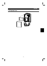
1.3.1 Appearance and structure
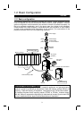
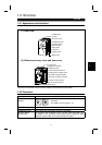
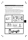
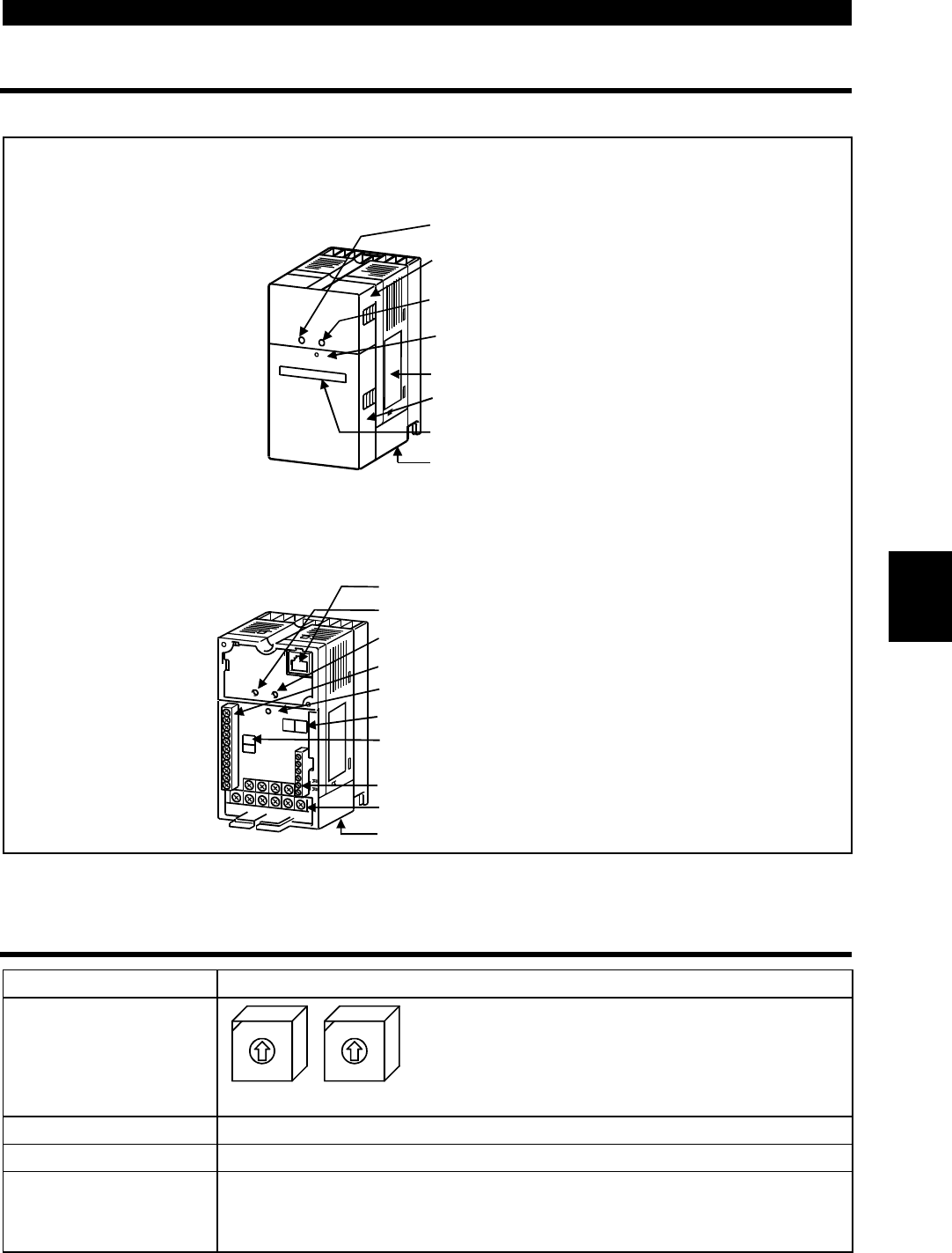
(1) Front view
POWER lamp
(yellow)
Accessory cover
ALARM lamp (red)
Operating status
indicator LEDs
Rating plate
Front cover
Capacity plate
Wiring cover
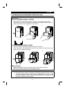
(2) Without accessory cover and front cover
POWER lamp (yellow)
Operating status indicator LEDs
Control logic changing connector
Control circuit terminal block
PU connector*
ALARM lamp (red)
DeviceNet
TM
terminal block
Main circuit terminal block
Wiring cover
Node address setting switches
* Use the PU connector for the FR-PU04 (option) and RS-485 communication.
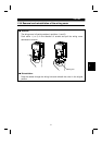
1.3.2 Functions
Name Function
Node address setting
switches
SW1(
×
10)
0
9
8
7
6
5
4
3
2
1
0
9
8
7
6
5
4
3
2
1
SW2(
×
1)
Used to set the inverter node address between
0 and 63.
For details, refer to page 47, 51.
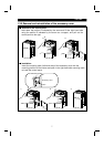
POWER lamp (yellow) Lit to indicate that power is input (present).
ALARM lamp (red) Lit to indicate that a protective function is activated.
Operating status
indicator LED
The operating status indicator LED is a 2 color (Red and Green) LED.
For details on the operating status please refer to page 25 which
details the system state and corresponding LED status.
1