


INSTALLATION AND WIRING
43
"
""
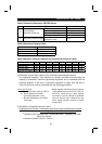
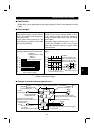
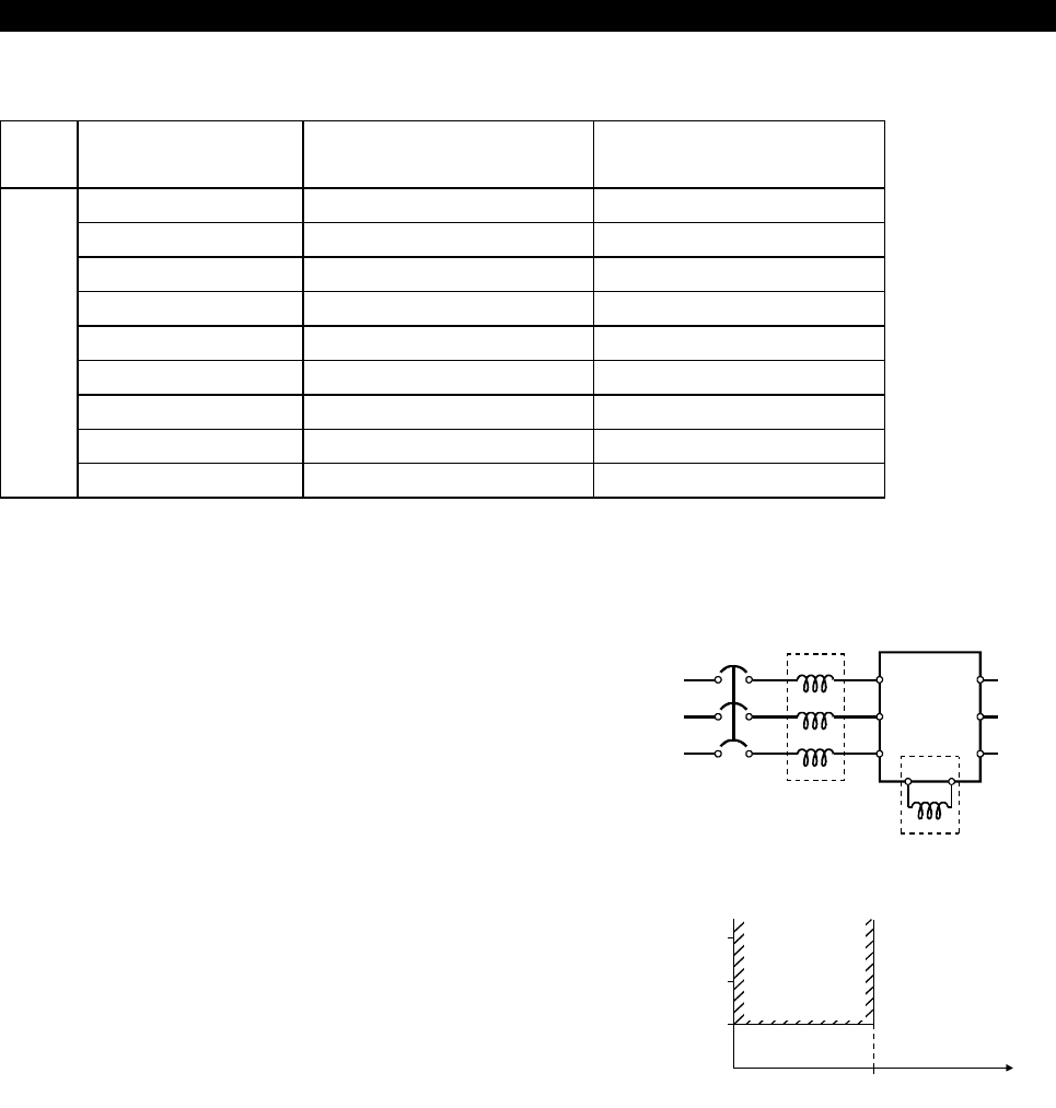
" Power factor improving reactor
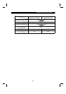
Inverter Model
Power Factor
Improving AC Reactor
Power Factor
Improving DC Reactor
FR-E520-0.1KND FR-BAL-0.4K (Note) FR-BEL-0.4K (Note)
FR-E520-0.2KND FR-BAL-0.4K (Note) FR-BEL-0.4K (Note)
FR-E520-0.4KND FR-BAL-0.4K FR-BEL-0.4K
FR-E520-0.75KND FR-BAL-0.75K FR-BEL-0.75K
FR-E520-1.5KND FR-BAL-1.5K FR-BEL-1.5K
FR-E520-2.2KND FR-BAL-2.2K FR-BEL-2.2K
FR-E520-3.7KND FR-BAL-3.7K FR-BEL-3.7K
FR-E520-5.5KND FR-BAL-5.5K FR-BEL-5.5K
Three-phase 200V
FR-E520-7.5KND FR-BAL-7.5K FR-BEL-7.5K
Note: The power factor may be slightly less.
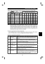
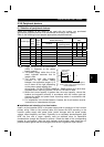
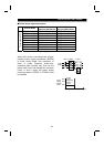
When the inverter is connected near a large-
capacity power supply transformer (500kVA
or more, wiring length 10m maximum) or
there is power capacitor switch-over,
excessive peak currents may flow into the
power input circuit and damage the converter
circuit. In such a case, the power supply
improving reactor (FR-BEL or FR-BAL) must
be installed.
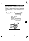
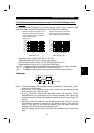
NFB
Inverter
FR-BAL
Power
supply
R
S
TZ
Y
X
R (L
1
)
S (L
2
)
T (L
3
)
U
V
W
PP1
FR-BEL
(+)
Power
factor
improving
reactor
range
010
500
1500
1000
Power
supply
capacit
y
(kVA)
Wirin
g
len
g
th
(
m
)