


159
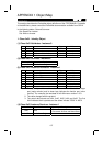
3. Class 0x04 - Assembly Object
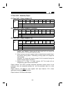
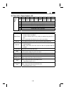
(1) Class 0x04 - Output Instance 20
Byte Bit 7 Bit 6 Bit 5 Bit 4 Bit 3 Bit 2 Bit 1 Bit 0
0
−−−−−
Fault
Reset
−
Run
Fwd
1
−
2 Speed Reference (Low Byte)
Instance
0x14
20
3 Speed Reference (High Byte)
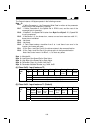
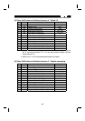
(2) Class 0x04 - Output Instance 21 (Default)
Byte Bit 7 Bit 6 Bit 5 Bit 4 Bit 3 Bit 2 Bit 1 Bit 0
0
−
NetRef NetCtrl
−−
Fault
Reset
Run
Rev
Run
Fwd
1
−
2 Speed Reference (Low Byte)
Instance
0x15
21
3 Speed Reference (High Byte)
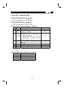
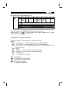
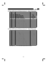
(3) Class 0x04 - Output Instance 126
Byte Bit7 Bit6 Bit5 Bit4 Bit3 Bit2 Bit1 Bit0
0
Write
Param
NetRef NetCtrl
−−
Fault
Reset
Run
Rev
Run
Fwd
100
2 (Low Byte) Speed Ref or Parameter Write Data
3 (High Byte) Speed Ref or Parameter Write Data
4 Parameter Class
Instance
0x7E
126
5 Parameter Attribute No.
Note 1. Before directing the inverter via the network, always turn on the bits of
"NetCtrl" and "NetRef". If they are off, the inverter will not accept the
directives even in the network operation mode.
2. When issuing a command, always hold the forward/reverse rotation flag in
the present running status. Transmitting a wrong status will change the
running status.
(Example: The inverter will stop the output if bit 0 is turned off during the
inverter forward rotation command.)
3. Always set "0" in Byte 1 of output instance 126. The inverter will not
recognize any other value as normal data.
Output Instance 126 (0x7E) provides write/read parameter access control of the
parameter class, the parameter attribute No., and the parameter data for a write
operation.
Output Instance 126
must
be used together with Input Instance 176 in those
applications requiring parameter access.
Output Instance 126 utilizes 6 data bytes.