


54
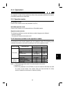
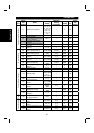
3.3.5 Operation on alarm occurrence
The following table shows the behavior of the inverter and network communication
operation on alarm occurrence.
Operation mode
Type of fault Item
Net mode PU mode
Inverter operation Stop Stop
Inverter (Note 3)
Network
communication
Continue Continue
Inverter operation Stop (Note 1) Continue
DeviceNet
(Note 4)
Communication
Network
communication
Continue
(Note 2)
Continue
(note 2)
Note: 1. Inverter operation stops on expiration of lnactivity/Watchdog timer of
Connection Object.
2. Depends on the type of communication fault.
3. Examples, E.OPT, E.OC1.
4. Examples, Status LED is Blinking Red LED, Red LED.
Please refer to Page 127 for more details.
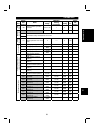
3.3.6 Inverter reset
Inverter reset behavior is as explained on page 53.
3.3.7 Setting frequency (f) value
Frequency setting in RAM can be made using Class 0x2A - Instance 1 - Attributes 112,
113. (Refer to Page 170)
3.3.8 Parameter clear (Pr Clr) commands
To execute the parameter clear commands, use Class 0x2A - Instance 1 - Attributes
102 to 106.
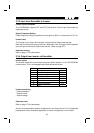
3.3.9 Control input commands
To send any control input command, use Class 0x2A - Instance 1 - Attribute 114. For
example, setting it with value 0x0002 will cause the inverter to run forward (FWD) at
the frequency value set in RAM.
Refer to the following bitmap tables for details:
76543210
0 0 RL * RM * RH * STR STF 0
15 14 13 12 11 10 9 8
00000MRS *00
* Input terminal function choices (Pr.180 to Pr.183) change terminal functions.
3