


PROTECTIVE FUNCTIONS
148
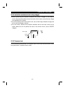
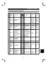
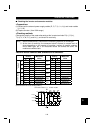
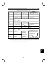
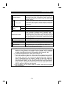
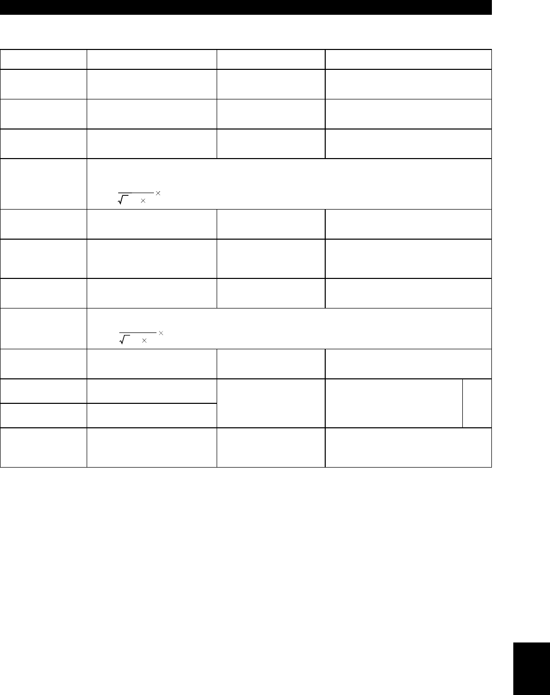
Measuring Points and Instruments
Item Measuring Point Measuring Instrument
Remarks
(Reference Measured Value)
Power supply
voltage
(V1)
Across R-S (L
1
-L
2
), S-T (L
2
-
L
3
) and T-R (L
3
-L
1
)
Moving-iron type AC
voltmeter
Is the commercial
p
ower su
pp
l
y
within
p
ermissible variation of AC volta
g
e
(Refer to page 149)
Power supply side
current
(I1)
R, S and T line currents
(L
1
, L
2
and L
3
line currents)
Moving-iron type AC
ammeter
Power supply side
power
(P1)
At R
(
L
1
)
, S
(
L
2
)
and T
(
L
3
)
,
and across R-S
(
L
1
-L
2
)
, S-T
(L
2
-L
3
) and T-R (L
3
-L
1
)
Electrodynamic type
single-phase wattmeter
P1 = W11 + W12 + W13
(3-wattmeter method)
Power supply side
power factor
(Pf1)
Calculate after measurin
g
p
ower su
pp
l
y
volta
g
e,
p
ower su
pp
l
y
side current and
p
ower su
pp
l
y
side
power.
Pf1 = 100 %
3V1 I1
P1
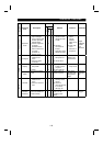
Output side
voltage
(V2)
Across U-V, V-W and W-U
(Note 1)
(Cannot be measured
by moving-iron type)
Difference between
p
hases is within
±
1% of maximum output voltage.
Out
p
ut side current
(I2)
U, V and W line currents
Moving-iron type AC
ammeter
(Note 2)
Current should be equal to or less than
rated inverter current.
Difference between
p
hases is 10% or
lower.
Output side power
(P2)
At U, V and W, and across U-
V and V-W
Electrodynamic type
single-phase wattmeter
P2 = W21 + W22
2-wattmeter method
(
or 3-wattmeter
method)
Output side power
factor
(Pf2)
Calculate in similar manner to power supply side power factor.
Pf2 = 100 %
3V2 I2
P2
Converter output Across P-N (+ -
−)
Moving-coil type
(such as tester)
Inverter LED display is lit. 1.35
×
V1
Maximum 380V during regenerative
operation
Reset Across RES (positive)-SD
Output stop Across MRS (positive)-SD
Moving-coil type
(Meter, etc. may be
used)
(Internal resistance:
50k
Ω
or larger)
20 to 30VDC when open.
ON voltage: 1V or less
SD is
common
Alarm signal
Across A-C
Across B-C
Moving-coil type
(such as a meter)
Continuity check
<Normal> <Fault>
Across A-C: DiscontinuityContinuity
Across B-C: Continuity Discontinuity
Note: 1. Use FFT to measure the output voltage accurately. It can not be measured accurately with a meter or
general instrumentation.
2. If the carrier frequency exceeds 5kHz, do not use this instrument since using it may increase eddy-
current loss produced in metal parts inside the instrument, leading to burnout.
In this case, use an approximate effective value type instrument.
5