


INSTALLATION AND WIRING
14
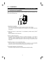
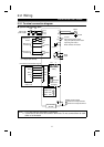
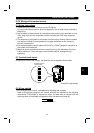
2.2.2 Wiring of the main circuit
(1) Wiring instructions
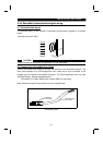
1) It is recommended to use insulation-sleeved solderless terminals for power supply
and motor wiring.
2) Power must not be applied to the output terminals (U, V, W) of the inverter.
Otherwise the inverter will be damaged.
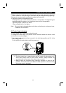
3) After wiring, wire off-cuts must not be left in the inverter.
Wire off-cuts can cause an alarm, failure or malfunction. Always keep the inverter
clean.
When drilling mounting holes in a control box etc., be careful so that chips and
others do not enter the inverter.
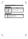
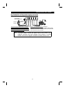
4) Use thick cables to make the voltage drop 2% or less.
If the wiring distance is long between the inverter and motor, a main circuit cable
voltage drop will cause the motor torque to decrease, especially at the output of a
low frequency. (A selection example for the wiring length of 20m is shown on page
16.)
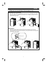
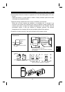
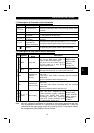
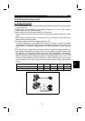
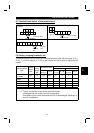
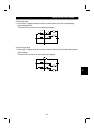
5) For long distance wiring, the overcurrent protection may be activated improperly or
the devices connected to the output side may misoperate or become faulty under
the influence of a charging current due to the stray capacitance of the wiring.
Therefore, the maximum overall wiring length should be as indicated in the following
table. If the wiring length exceeds the value, it is recommended to set "1" in Pr. 156
to make the fast-response current limit function invalid. (When two or more motors
are connected to the inverter, the total wiring length should be within the indicated
value.)
Inverter Capacity 0.1K 0.2K 0.4K 0.75K
1.5K
or more
Non-low acoustic noise mode 200m 200m 300m 500m 500m
Low acoustic noise mode 30m 100m 200m 300m 500m
Overall wiring length (1.5K or more)
500m maximum
300m
300m
300m+300m=600m
2