


INSTALLATION AND WIRING
30
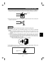
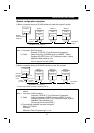
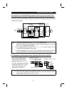
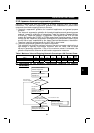
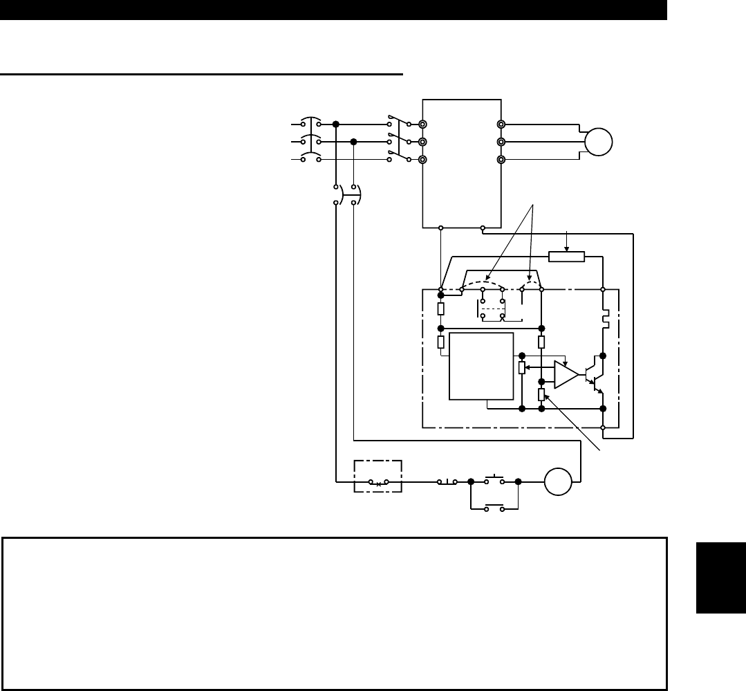
(2) Connection of the BU brake unit (option)
Connect the BU brake unit correctly
as shown on the right. Incorrect
connection will damage the inverter.
MC
R (L
1
)
S (L
2
)
T (L
3
)
U
V
W
Motor
IM
Inverter
HCHBHA
TB
HC HB
ON
Brake unit
MC
MC
OFF
P (+)
N (-)
P
OCR
Discharge resistor
Remove jumpers.
PR
OCR
-
+
BU brake unit
N
NFB
Constant-
voltage
power
supply
Comparato
r
PC
Note:1. The wiring distance between the inverter, brake unit and discharge resistor
should be within 2m. If twisted wires are used, the distance should be within
5m.
2. If the transistors in the brake unit should fail, the resistor will be extremely
hot, causing a fire. Therefore, install a magnetic contactor on the inverter's
power supply side to shut off current in case of failure.
2