


INSTALLATION AND WIRING
16
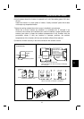
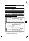
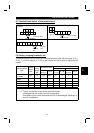
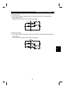
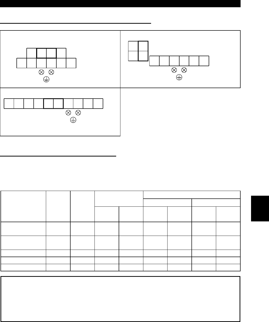
(2) Terminal block layout of the power circuit
FR-E520-0.1KND, 0.2KND, 0.4KND,
0.75KND
P1
N/- P/+ PR
R/L
1
S/L
2
T/L
3
UVW
Screw size (M3.5)
TB1
Screw size (M3.5)
FR-E520-1.5KND, 2.2KND, 3.7KND
P1
N/- P/+
PR
R/L
1
S/L
2
T/L
3
UVW
Screw size
(
M4
)
TB1
TB2
Screw size (M4)
Screw size
(
M4
)
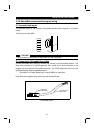
FR-E520-5.5KND, 7.5KND
P1
PR V WP/+
R/L
1
S/L
2
T/L
3
N/-
U
Screw size
(M5)
TB1
Screw size
(M5)
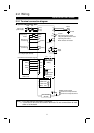
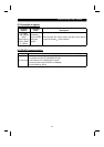
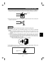
(3) Cables, crimping terminals, etc.
The following table lists the cables and crimping terminals used with the inputs (R (L
1
),
S (L
2
), T (L
3
)) and outputs (U, V, W) of the inverter and the torques for tightening the
screws:
Cables
Crimping Terminals
mm
2
AWGApplicable Inverter
Type
Terminal
Screw
Size
Tight-
ening
Torque
N
⋅
⋅⋅
⋅
m
R, S, T
(L
1
, L
2
, L
3
)
U, V, W
R, S, T
(L
1
, L
2
, L
3
)
U, V, W
R, S, T
(L
1
, L
2
, L
3
)
U, V, W
FR-E520-0.1KND
to 0.75KND
M3.5 1.2 2-3.5 2-3.5 2 2 14 14
FR-E520-1.5KND,
2.2KND
M4 1.5 2-4 2-4 2 2 14 14
FR-E520-3.7KND M4 1.5 5.5-4 5.5-4 3.5 3.5 12 12
FR-E520-5.5KND M5 2.5 5.5-5 5.5-5 5.5 5.5 10 10
FR-E520-7.5KND M5 2.5 14-5 8-5 14 8 6 8
Note:1. The cables used should be 75
°
C copper cables.
2. Tighten the terminal screws to the specified torques.
Undertightening can cause a short or misoperation.
Overtightening can cause the screws and unit to be damaged, resulting in a
short or misoperation.
2