


INSTALLATION AND WIRING
23
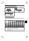
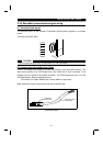
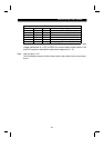
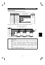
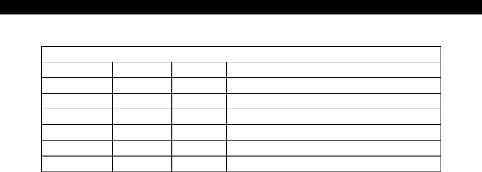
Pin Out/Functions
Pin No. Color Name Signal Type
1 Red V+ Power cable positive end (V+)
2 White CAN+ Communication data high side (CAN H)
3 Bare SHLD Drain
4 Blue CAN- Communication data low side (CAN L)
5 Black V- Power cable negative end (V-)
6—— —
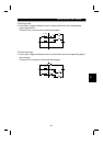
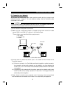
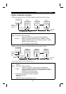
DeviceNet has a voltage specification of 24VDC for communication and an input
voltage specification of 11VDC to 25VDC for communication to each device. A 5V
drop in the system is stipulated for each power supply wire (V+, V-).
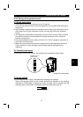
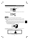
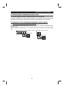
Note: Use only pins 1 to 5.
The DeviceNet connector of the inverter has a 6-pin socket, but do not connect
6 pins.