


INSTALLATION AND WIRING
42
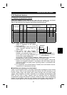
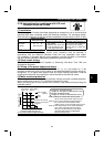
2.3.5 Peripheral devices
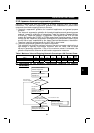
(1) Selection of peripheral devices
Check the capacity of the motor to be used with the inverter you purchased.
Appropriate peripheral devices must be selected according to the capacity.
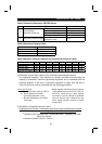
Refer to the following list and prepare appropriate peripheral devices:
No-Fuse Breaker (NFB) or Earth Leakage Circuit
Breaker (NV) (Note 5)
Magnetic Contactor
(MC)
Inverter Type
Motor
Output
(kW)
Power
Supply
Capacity
(kVA)
Standard
With power factor
improving reactor
ABC
FR-E520-0.1K 0.1 0.4 30AF 5A 30AF 5A S-N11 S-N18 S-N20
FR-E520-0.2K 0.2 0.8 30AF 5A 30AF 5A S-N18 S-N20 S-N20
FR-E520-0.4K 0.4 1.5 30AF 5A 30AF 5A S-N18 S-N21 S-N21
FR-E520-0.75K 0.75 2.5 30AF 10A 30AF 10A S-N18 S-N21 S-N21
FR-E520-1.5K 1.5 4.5 30AF 15A 30AF 15A S-N21 S-N25 S-N50
FR-E520-2.2K 2.2 5.5 30AF 20A 30AF 15A S-N11,S-N12
FR-E520-3.7K 3.7 9 30AF 30A 30AF 30A S-N20
FR-E520-5.5K 5.5 12 50AF 50A 50AF 40A S-N25
Three-phase 200V
FR-E520-7.5K 7.5 17 100AF 60A 50AF 50A S-N35
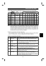
Note:1. Select the t
y
pe of the no-fuse breaker
(
NFB
)
in response to the power
supply capacity.
2. The power suppl
y
cable size of the
motor indicated assumes that its
length is 20m.
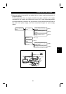
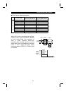
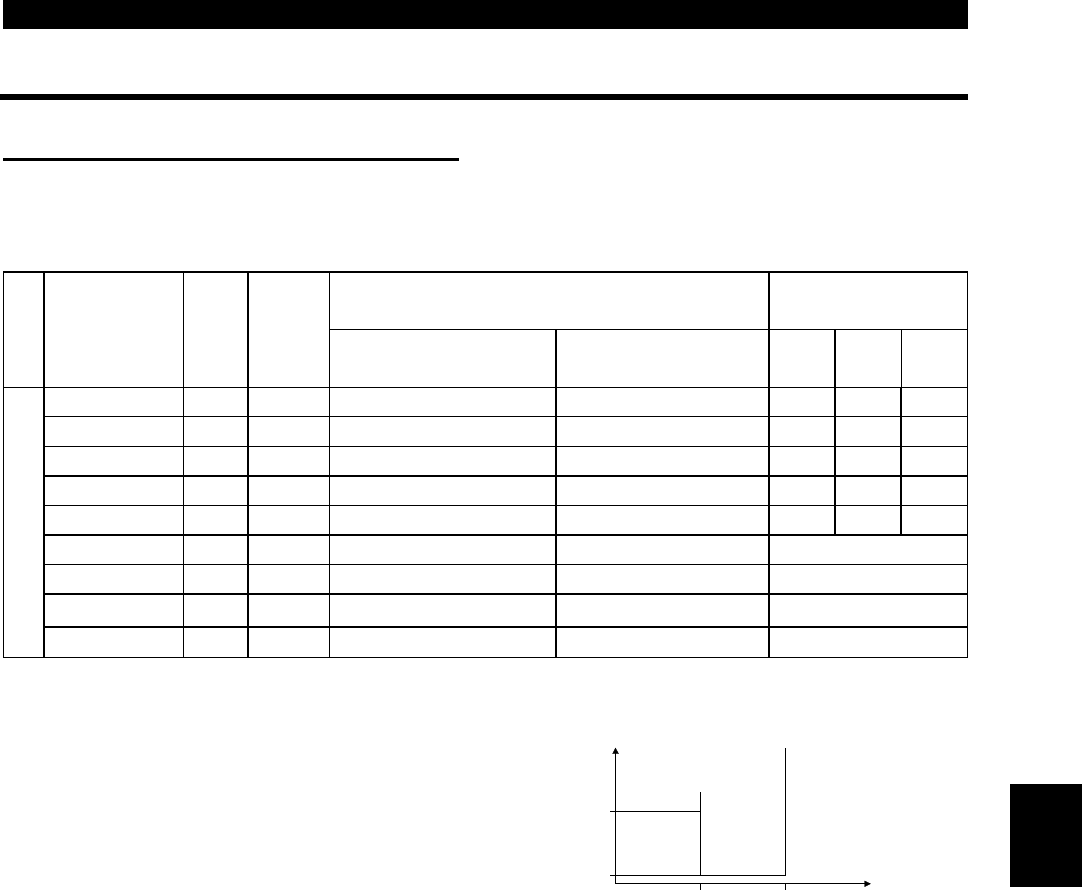
3. The inverter input side magnetic
contactor to be chosen differs
between the applicable ranges A, B
and C shown on the right, depending
on the power supply capacity and
Power factor
improving
AC reactor
range
AB
C
Note: Power supply used has the above
recommended size.
0 10 20 Wiring length(m)
50
500
Power supply capacity(kVA)
wirin
g
len
g
th. For the FR-E520-0.4KND to 1.5KND choose the S-N10 when
the power factor improving reactor (FR-BEL or FR-BAL) is used.
4. When the inverter capacit
y
is
g
reater than the motor capacit
y
, choose the
breaker and ma
g
netic contactor in accordance with the inverter t
y
pe and
choose the cables and power factor improvin
g
reactor in accordance with
the motor output.
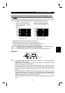
5. For installations in the United States or Canada, the circuit breaker must be
inverse time or instantaneous trip type.
"
""
"
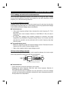
Installation and selection of no-fuse breaker
Install a no-fuse breaker (NFB) in the power supply side for protection of the inverter's
primary wiring. Refer to the previous table and choose the NFB according to the
inverter's power supply side power factor (which changes with the power supply
voltage, output frequency and load). Especially for a completely electromagnetic type
NFB, the one with a larger capacity must be selected since its operational
characteristics change with harmonic currents. (Check the data of the corresponding
breaker for confirmation.) Also the earth leakage circuit breaker used should be our
product durable against harmonics/surges (such as the Progressive Super Series).
2