


PARAMETERS
105
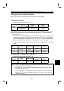
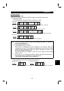
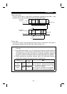
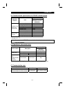
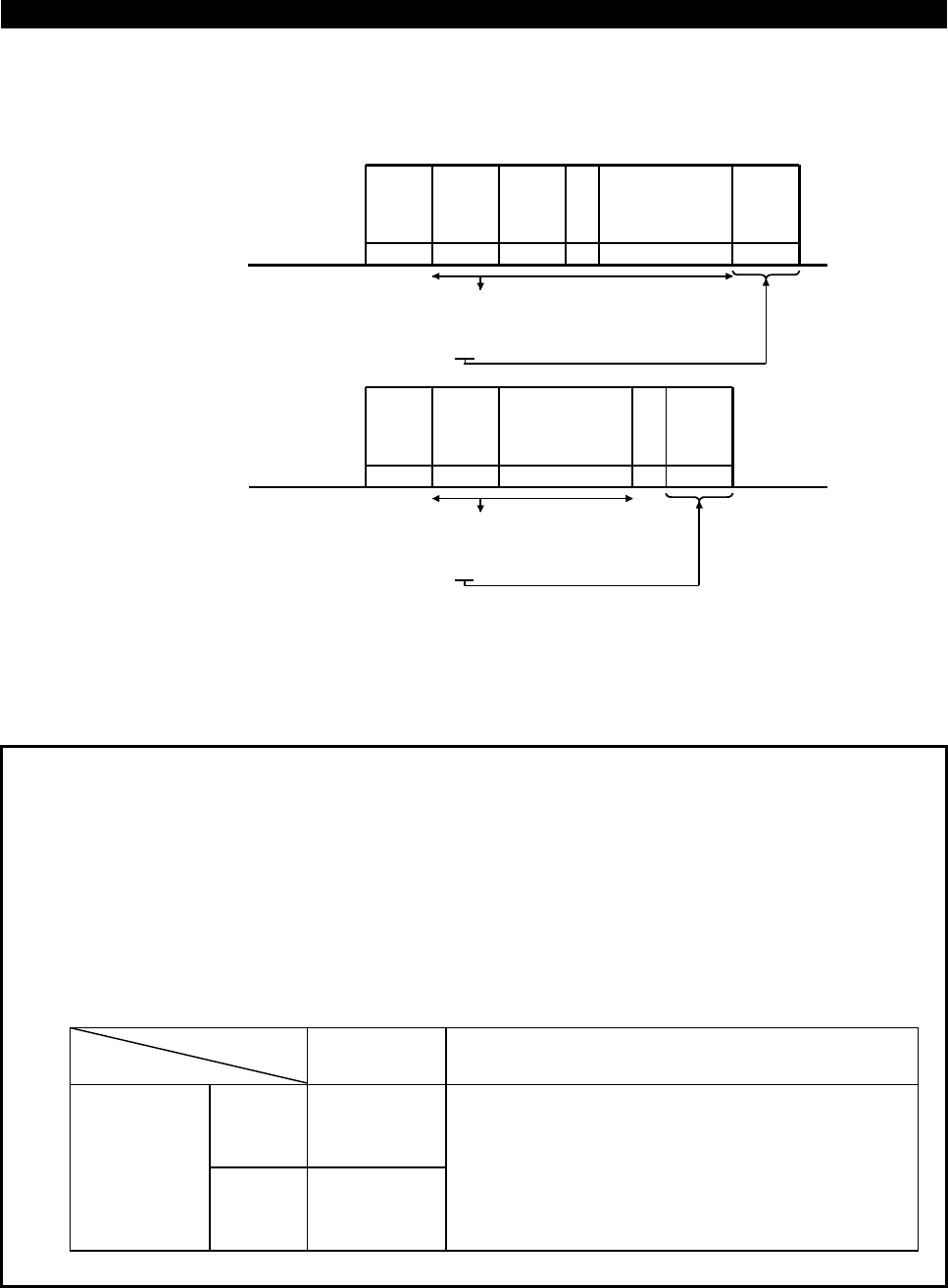
7) Sum check code
The sum check code is 2-digit ASCII (hexadecimal) representing the lower 1 byte
(8 bits) of the sum (binary) derived from the checked ASCII data.
30
+
31
+
45
+
31
+
31
+
30
+
37
+
41
+
44
=
1F4
E
N
Q
1
0 1E1 07ADF4
H05 H30 H31 H31H45 H31 H30 H37 H41 H44 H46 H34
S
T
X
0 117030
H02 H30 H31 H37H31 H37 H30 H03 H33 H30
E
T
X
7
(Example 1)
Computer
→
inverter
ASCII code
→
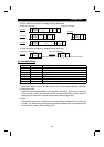
(Example 2)
inverter
→
Computer
ASCII code
→
Station
number
Instruction
code
Data
Sum
check
code
H
HHHHHHHH
H
H
30
+
31
+
31
+
37
+
37
+
30
=
130
HHHHH
H
Station
number
Sum
check
code
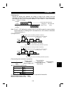
Read time
←
Binary code
←
Binary code
Waiting
time
Sum
Sum
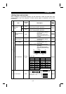
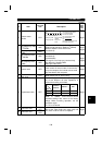
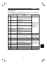
8) Error code
If any error is found in the data received by the inverter, its definition is sent back to
the computer together with the NAK code. (Refer to page 110.)
Note:1. When the data from the computer has an error, the inverter will not accept
that data.
2. Any data communication, e.g. run command, monitoring, is started when the
computer gives a communication request. Without the computer's command,
the inverter does not return any data. For monitoring, therefore, design the
program to cause the computer to provide a data read request as required.
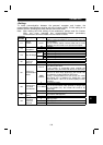
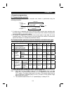
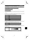
3. When accessing the parameter settings, data for link parameter expansion
setting differs between the parameters as indicated below:
Instruction
Code
Data
Read H7F
Link
parameter
expansion
setting
Write HFF
H00: Pr. 0 to Pr. 96 values are accessible.
H01: Pr. 100 to Pr. 156 values are accessible.
H02: Pr. 160 to Pr. 196 and Pr. 232 to Pr. 250
values are accessible.
H03: Pr. 345 to Pr. 348 values are accessible.
H09: Pr. 990, Pr. 991 values are accessible.