


INSTALLATION AND WIRING
41
2.3.4 Leakage currents and countermeasures
Due to the static capacitance existing in the inverter I/O wiring and motor, leakage
currents flow through them. Since their values depend on the static capacitance, carrier
frequency, etc., take the following measures.
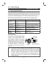
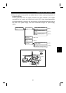
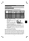
(1) To-ground leakage currents
Leakage currents may flow not only into the inverter's own line but also into the other
lines through the ground cable, etc. These leakage currents may operate earth leakage
circuit breakers and earth leakage relays unnecessarily.
"
""
"
Countermeasures
!
If the carrier frequency setting is high, decrease the carrier frequency (Pr. 72) of
the inverter.
Note that motor noise increases. Selection of Soft-PWM (Pr. 240) will make it
unoffending.
!
By using earth leakage circuit breakers designed for harmonic and surge
suppression (e.g. Mitsubishi's Progressive Super Series) in the inverter's own line
and other line, operation can be performed with the carrier frequency kept high
(with low noise).
"
""
"
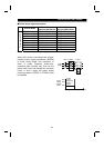
To-ground leakage current
!
Note that a long wiring length will increase leakage currents. Decrease the carrier
frequency of the inverter to reduce leakage currents.
!
Higher motor capacity leads to larger leakage currents.
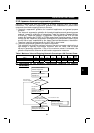
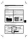
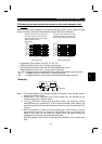
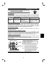
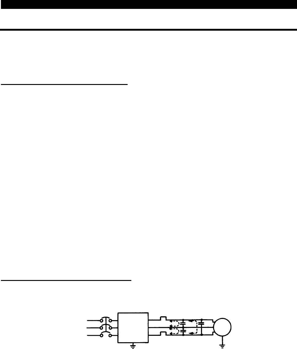
(2) Line-to-line leakage currents
Harmonics of leakage currents flowing in static capacities between the inverter output
cables may operate the external thermal relay unnecessarily.
Inverter
Power
suppl
y
IM
Thermal relay
Line static capacitances
NFB
Line-to-line leakage current path
Motor
"
""
"
Countermeasures
!
Use the electronic overcurrent protection of the inverter.
!
Decrease the carrier frequency. Note that motor noise increases. Selection of
Soft-PWM will make it unoffending.
To ensure that the motor is protected not to be influenced by line-to-line leakage
currents, we recommend the protection method which uses a temperature sensor to
directly detect motor temperature.