


INSTALLATION AND WIRING
40
"
""
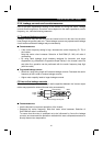
" Data line filter
Noise entry can be prevented by providing a data line filter for the detector or other
cable.
"
""
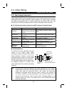
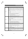
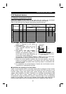
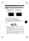
" Data examples
By decreasing the carrier frequency, the
noise terminal voltage* can be reduced.
Use Pr. 72 to set the carrier frequency to
a low value (1kHz).
Though motor noise increases at a low
carrier frequency, selection of Soft-PWM
will make it unoffending.
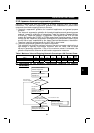
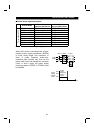
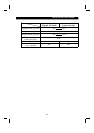
By using shielded cables as signal cables,
induction noise can be reduced greatly (1/10 to
1/100). Induction noise can also be reduced by
moving the signal cables away from the inverter
output cables.
(Separation of 30cm reduces noise to 1/2 to 1/3.)
By fitting the FR-BSF01 or BLF on the inverter
output side, induction noise to the signal cables
can be reduced.
Differences between noise terminal
voltages at different carrier frequencies
0
20
40
60
80
100
120
0.1 1 10
Noise fre
q
uenc
y
(
MHz
)
Noise terminal voltage (dB)
Conditions
Average terminal
volta
g
e
0dB=1
µ
V
120dB=1V
Carrier frequency 10kHz
Carrier frequency 1kHz
Noise induced to signal cables by inverter output
cables
5cm
Line-to-line distance d (cm)
20
40
60
80
100
10
0
20 30 40 50
Induction voltage (dB)
d(cm)
Motor
Measurin
g
instrumen
t
Terminal
Inverter
FR-BLF
FR-BSF01
(4T)
Conditions
Inverter: FR-E520-3.7K
Motor: FR-JR 4P 3.7kW
Output frequency: 30Hz
Noise form: Normal mode
Parallel cable
Twisted pair cable
Coaxial cable
* Noise terminal voltage: Represents the magnitude of noise propagated from the
inverter to the power supply.
"
""
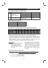
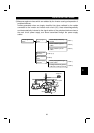
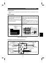
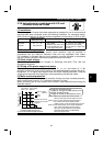
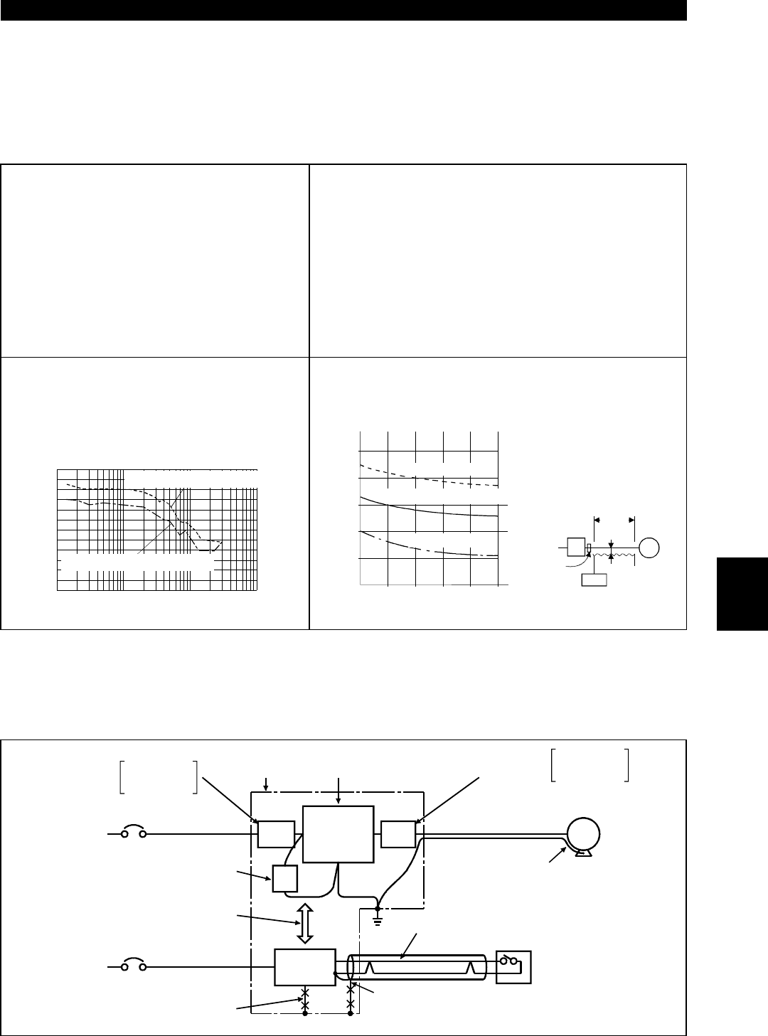
" Example of counter measures against noise
Inverter
FR-
BIF
Sensor
Use 4-core cable for motor power
cable and use one wire as earth cable.
Power supply
for sensor
Use twisted pair shielded cable.
Inverter
power supply
Control power
supply
Do not ground shield but connect it to signal
common cable.
Do not ground control
box directly.
Do not
g
round control cable.
S
eparate inverter and power
line 30cm or more
(
at least 10cm
)
f
rom sensor circuit.
Install filter FR-BIF to
inverter input side.
Control box
Reduce carrier frequency.
Motor
IM
FR-
BSF01
FR-
BSF01
FR-BLF
FR-BSF01
Install filter
to inverter input side.
FR-BLF
FR-BSF01
Install filter to
inverter output side.
2