INSTALLATION AND WIRING
19
2) When using bar terminals and solid wires for wiring, their diameters should be
0.9mm maximum. If they are larger, the threads may be damaged during tightening.
3) Loosen the terminal screw and insert the cable into the terminal.
4) Tighten the screw to the specified torque.
Undertightening can cause cable disconnection or misoperation. Overtightening can
cause damage to the screw or unit, leading to short circuit or misoperation.
Tightening torque: 0.25N
⋅
m to 0.49N
⋅
m
*Use a screwdriver No. 0 to tighten.
Note: When routing the stripped cables, twist them so that they do not become loose.
In addition, do not solder it.
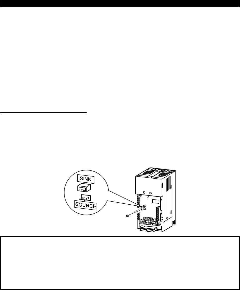
(4) Control logic changing
The input signal logic is factory-set to the sink mode.
To change the control logic, the position of the connector beside the control circuit
terminal block must be changed.
1) Use tweezers etc. to remove the connector in the sink logic position and fit it in the
source logic position.
Do this position changing before switching power on.
Note:1. Make sure that the front cover has been installed securely.
2. The front cover has a capacity plate and the inverter a rating plate on it.
Since these plates have the same serial numbers, always reinstall the
removed cover to the inverter from where it was removed.
3. Always install the sink-source logic changing connector in either of the
positions. If two connectors are installed in these positions at the same time,
the inverter may be damaged.
