


SPECIFICATIONS
151
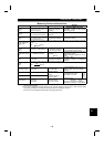
Operation functions
Maximum/minimum frequency setting, frequency jump operation,
external thermal relay input selection, automatic restart operation after
instantaneous power failure, forward/reverse rotation prevention, slip
compensation, operation mode selection, offline auto tuning function
DeviceNet operation.
Control specifications
Output signals
Operating status
1 contact output (230VAC 0.3A, 30VDC 0.3A) can be selected from
inverter running, up to frequency, frequency detection, overload alarm,
zero current detection, output current detection, operation ready, minor
fault and alarm.
Operating
status
Output voltage, output current, set frequency, running.
Control panel
display
Alarm
definition
Alarm definition is displayed when protective function is activated. 4
alarm definitions are stored.
Display
LED display Power application (POWER), Alarm (ALARM), Operating status
Protective/alarm functions
Overcurrent shut-off (during acceleration, deceleration, constant
speed), regenerative overvoltage shut-off, undervoltage (Note 1),
instantaneous power failure (Note 1), overload shut-off (electronic
overcurrent protection), brake transistor alarm, output short circuit, stall
prevention, brake resistor overheat protection, fin overheat, fan failure
(Note 4), parameter error, PU disconnection, starting-time ground fault
overcurrent protection.
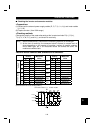
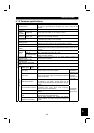
Ambient temperature Constant torque : -10
°
C to +50
°
C (non-freezing)
Ambient humidity 90%RH or less (non-condensing)
Storage temperature (Note 2) -20
°
C to +65
°
C
Ambience Indoors (no corrosive and flammable gases, oil mist, dust and dirt.)
Environment
Altitude, vibration
Maximum 1000m above sea level for standard operation.
After that derate by 3% for every extra 500m up to 2500m (91%).
5.9m/s
2
or less (conforming to JIS C 0040)
Note:1. When undervolta
g
e or instantaneous power failure has occurred, alarm
displa
y
or alarm output is not provided but the inverter itself is protected.
Overcurrent, re
g
enerative overvolta
g
e or other protection ma
y
be activated
at power restoration according to the operating status (load size, etc.)
2. Temperature applicable for a short period in transit, etc.
3. The brakin
g
torque indicated is a short-duration avera
g
e torque
(
which
varies with motor loss
)
when the motor alone is decelerated from 60Hz in
the shortest time and is not a continuous re
g
enerative torque. When the
motor is decelerated from the frequenc
y
hi
g
her than the base frequenc
y
,
the avera
g
e deceleration torque will reduce. Since the inverter does not
contain a brake resistor, use the optional brake resistor when re
g
enerative
ener
gy
is lar
g
e.
(
The optional brake resistor cannot be used with 0.1K and
0.2K.) A brake unit (BU) may also be used.
4. Not provided for the FR-E520-0.1KND to 0.4KND which are not equipped
with a cooling fan.