


INSTALLATION AND WIRING
27
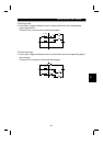
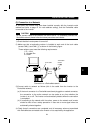
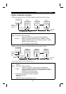
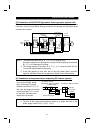
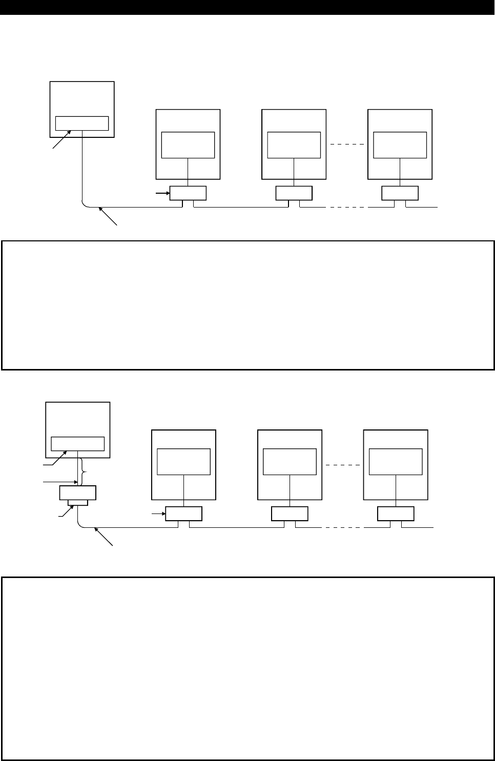
<System configuration examples>
1) When a computer having a RS-485 interface is used with several inverters
PU connector
(Note1)
Computer
RS-485
interface/terminal
Computer
10BASE-T cable
(
Note 2
)
Distribution
terminal
Station 1
Inverter
Station 2
Inverter
Station n
Inverter
Termination
resistor
PU connector
(Note1)
PU connector
(Note1)
Use the connectors and cables which are available on the market.
Note: 1. Connector: RJ45 connector
Example: 5-554720-3, Tyco Electronics Corporation
2. Cable : Cable conforming to EIA568 (such as 10BASE-T cable)
Example: SGLPEV 0.5mm
×
4P (Twisted pair cable, 4 pairs),
Mitsubishi Cable Industries, Ltd.
(Do not use pins 2) and 8) (P5S).)
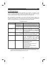
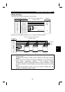
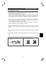
2) When a computer having a RS-232C interface is used with inverters
Computer
RS-232C
connector
RS-232C
cable
RS-485
terminal
Max. 15m
Converter*
Termination
resistor
Distribution
terminal
*Commercially available converter is required. (Note 3)
10BASE-T cable (Note 2)
PU connector
(Note1)
Station 1
Inverter
PU connector
(Note1)
Station 2
Inverter
PU connector
(Note1)
Station n
Inverter
Use the connectors, cables and converter which are available on the
market.
Note:1. Connector: RJ45 connector
Example: 5-554720-3, Tyco Electronics Corporation
2. Cable : Cable conforming to EIA568 (such as 10BASE-T cable)
Example: SGLPEV 0.5mm
×
4P (Twisted pair cable, 4 pairs),
Mitsubishi Cable Industries, Ltd.
(Do not use pins 2) and 8) (P5S).)
3.*Commercially available converter examples
Model: FA-T-RS40
Converter
Mitsubishi Electric Engineering Co., Ltd.