


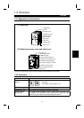
2.2 Wiring
INSTALLATION AND WIRING
11
2.2 Wiring
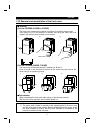
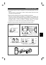
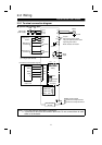
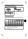
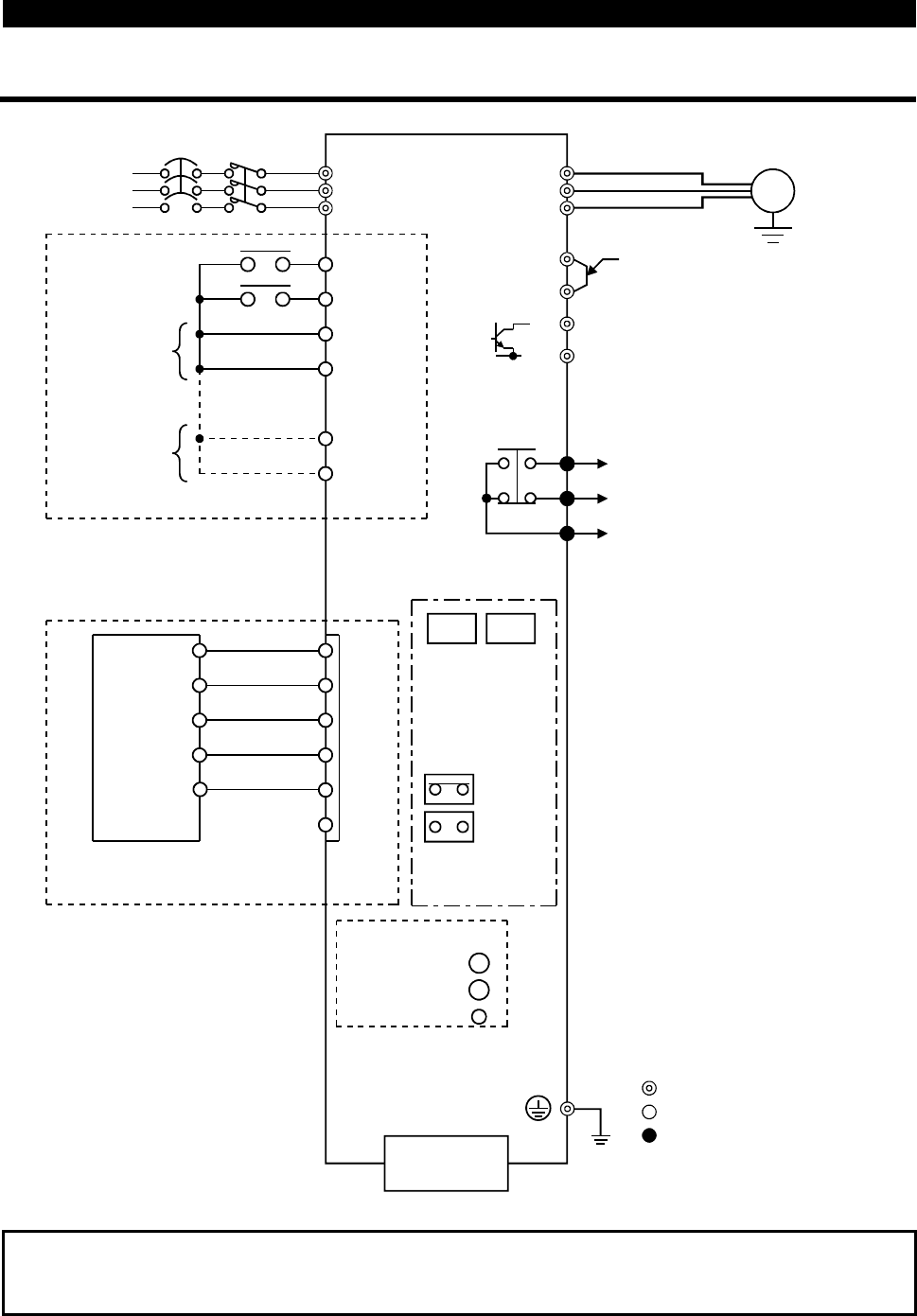
2.2.1 Terminal connection diagram
"
""
"
3-phase 200V power input
R
S
T
MRS
RES
SD
SD
P24
P24
A
B
C
U
V
W
P1
(
+
)P
PR
(
−
)N
(Note 1)
(Note 2)
(Note 2)
V+
CAN+
SHLD
NC
V+
CAN+
SHLD
CAN-
SW1 SW2
SINK
SOURCE
POWER LED
ALARM LED
L.RUN LED
3-phase AC
power supply
NFB
Output stop
Reset
Control input signals
(no voltage input allowed)
Jumper
Remove this jumper when
using the optional power-factor
improving DC reactor.
Brake resistor connection
Motor
IM
Ground
Alarm
output
Main circuit terminal
Control circuit input terminal
Control circuit output terminal
Ground
PU connector
(RS-485)
Sink input
commons
Source input
commons
DeviceNet communication signals
DeviceNet
master unit
Node address
setting
Sink/source
changing
(Indicator)
(L
1
)
(L
2
)
(L
3
)
MC
CAN-
V-
V-
×
10
×
1
Note:1. 0.1K and 0.2K do not contain a transistor.
2. Terminals SD and P24 are common terminals. Do not connect them to each
other or to the earth.