


INSTALLATION AND WIRING
46
2.3.6 Instructions for compliance with U.S. and
Canadian Electrical Codes
(Standard to comply with: UL 508C)
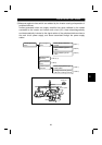
(1) Installation
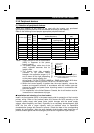
The above types of inverter have been approved as products for use in enclosure and
approval tests were conducted under the following conditions. For enclosure design,
refer to these conditions so that the ambient temperature of the inverter is 50
°
C or less.
Inverter Type
Cabinet (enclosure)
Size (Unit: mm)
Vent Hole Area Cooling Fan
FR-E520 -
3.7KND
W H D
255
×
192
×
218
•
55% of both the side of
the Cabinet
•
Width of each slit: 3.2mm
•
To be provided on each
of the upper side areas.
Installed at the enclosure top
to suck air from inside the
enclosure to the outside.
(Fan air flow: 2
×
0.59m
3
/min
or more)
(2) Branch circuit protection
For installation in United States, branch circuit protection must be provided, in
accordance with the National Electrical Code and any applicable local codes.
For installation in Canada, branch circuit protection must be provided in accordance
with the Canada Electrical Code and any applicable provincial codes.
(3) Short circuit ratings
Suitable For Use In A Circuit Capable of Delivering Not More Than 5kA rms
Symmetrical Amperes.
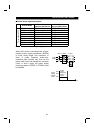
(4) Wiring of the power supply and motor
Screw the cables wired to the input (R, S, T) <L
1
, L
2
, L
3
> and output (U, V, W)
terminals and control circuit of the inverter to the specified tightening torque using UL-
recognized, 75
°
or higher rated copper wires and round crimping terminals. Crimp the
crimping terminals with the crimping tool recommended by the terminal maker.
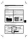
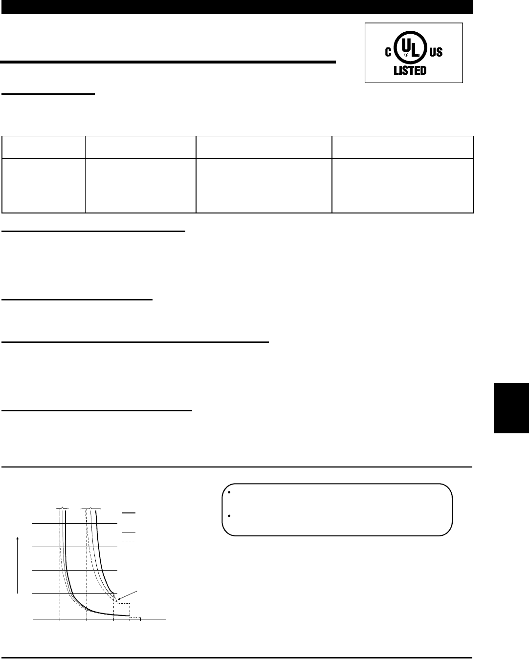
(5) Motor overload protection
When using the electronic overcurrent protection function as motor overload protection,
set the rated motor current in Pr. 9 "electronic thermal O/L relay".
When connecting two or more motors to the inverter, install external thermal relays for
individual motors.
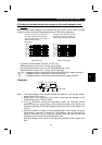
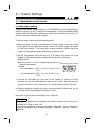
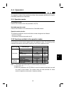
Reference: Motor overload protection characteristics
0 50 100 150 180200
240
180
120
60
Operation time (s)
50% setting
(Note 1, 2)
100% setting
(Note 2)
(Note 1) When you set the 50% value (current
value) of the rated inverter output current.
(Note 2) The % value denotes the percentage of
the current value to the rated inverter
output current, not to the rated motor current.
(Note 3) This characteristic curve will be described
even under operation of 6Hz or higher
when you set the electronic overcurrent
protection dedicated to the Mitsubishi
constant-torque motor.
30Hz or higher
(Note 3)
Inverter output current (%)
(% to rated inverter output current)
Electronic overcurrent
protection for transistor
protection
20Hz
10Hz
Protection activating range
Range on the right of characteristic curve
Normal operating range
Range on the left of characteristic curve
2