


INSTALLATION AND WIRING
31
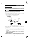
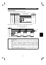
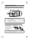
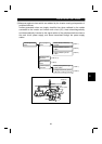
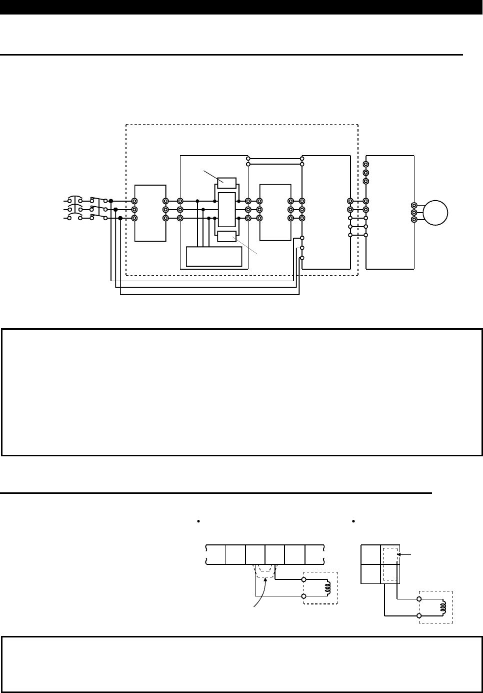
(3) Connection of the FR-HC high power factor converter (option unit)
When connecting the high power factor converter (FR-HC) to suppress power
harmonics, wire as shown below. Wrong connection will damage the high power factor
converter and inverter.
Inverter
(FR-E500)
IM
High power
factor converter
(FR-HC)
External box
(FR-HCB)
Reactor 2
(FR-HCL02)
R (L
1
)
Resistor
Reactor 1
(FR-HCL01)
Power
supply
Filter
capacitor
Phase
detection
S (L
2
)
T (L
3
)
P (+)
N (-)
MRS
RES
SD
U
V
W
P
N
RDY
RSO
SE
R
S
T
R4
S4
T4
R3
S3
T3
R3
S3
T3
MC
R2
S2
T2
R2
S2
T2
R
S
T
MC
NFB
MC1
MC2
Motor
Resistor
MC1
MC2
R4
S4
T4
Note:1. The power input terminals R, S, T (L
1
, L
2
, L
3
) must be open.
Incorrect connection will damage the inverter. Reverse polarity of terminals
N (
−
), P (+) will damage the inverter.
2. The voltage phases of terminals R, S, T (L
1
, L
2
, L
3
) and terminals R4, S4,
T4 must be matched before connection.
3. If the load capacity is less than half of the high power factor converter
capacity, satisfactory harmonic suppression effects cannot be produced.
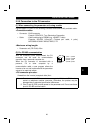
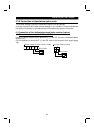
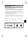
(4) Connection of the power factor improving DC reactor (option)
Connect the FR-BEL power
factor improving DC reactor
between terminals P1-P (+). In
this case, the jumper connected
across terminals P1-P (+) must
be removed. Otherwise, the
reactor will not function.
P1
P
FR-BEL
Remove the jumper.
P1
P
FR-BEL
Remove
the jumper.
FR-E520-1.5KND to 3.7KND
<Connection method>
FR-E520-0.1KND to 0.75KND,
5.5KND,7.5KND
PR
N
(-)
(+)
(+)
Note:1. The wiring distance should be within 5m.
2. The size of the cables used should be equal to or larger than that of the
power supply cables (R (L
1
), S (L
2
), T (L
3
)).